Device and method for diagnosing evaporation leak, and control device of internal combustion engine

a control device and leakage technology, applied in the direction of instruments, combustion air/fuel air treatment, fluid tightness measurement, etc., can solve the problems of insufficient negative pressure, insufficient negative pressure, and insufficient diagnosis frequency, so as to reduce the required diagnosis time, prevent the tank from deteriorating, and prevent the battery from being exhausted

Inactive Publication Date: 2007-08-14
HITACHI LTD
View PDF15 Cites 14 Cited by
  • Summary
  • Abstract
  • Description
  • Claims
  • Application Information

AI Technical Summary

Benefits of technology

[0033]Consequently, the present invention makes it possible, for instance, to reduce the required diagnosis time, prevent vapor from being discharged out of the vehicle, prevent the tank from deteriorating, and prevent the battery from being exhausted. Further, when diagnoses are made in accordance with pressure changes that are encountered while the pump is driven or stopped, the present invention makes it possible, for instance, to avoid a diagnosis error due to evaporation, avoid a diagnosis error at the time of canister pressure loss increase, and avoid a diagnosis error at the time of pump deterioration. Further, it can be expected that the present invention will reduce the amount of exhaust while judging fuel properties to assure stable startup performance. Moreover, the present invention makes it possible to judge the properties of fuel in the fuel tank by making effective use of information generated by the evaporation leak diagnostic device and provide increased stability and improved exhaust at the time of engine startup.

Problems solved by technology

However, the use of the negative pressure method has not provided an adequate diagnosis frequency in the market.
One reason is that the negative pressure is insufficient during a high-load operation.
The above-mentioned technologies do not provide any solution to establish such measures.
If the gradient of tank pressure increase is great before time C is reached, it is judged that there is a leak.
However, if a slosh occurs during the use of the conventional negative pressure method, a leak may be erroneously detected due to the influence of evaporation pressure even when there is no leak.
That is why it has been difficult to provide an adequate diagnosis frequency in the market.

Method used


Image

  • Device and method for diagnosing evaporation leak, and control device of internal combustion engine
  • Device and method for diagnosing evaporation leak, and control device of internal combustion engine
  • Device and method for diagnosing evaporation leak, and control device of internal combustion engine

Examples


Embodiment Construction

[0058]Preferred embodiments of the present invention will now be described with reference to the accompanying drawings.

[0059]First of all, a typical vehicle internal combustion engine system according to the present invention will be described with reference to FIG. 1.

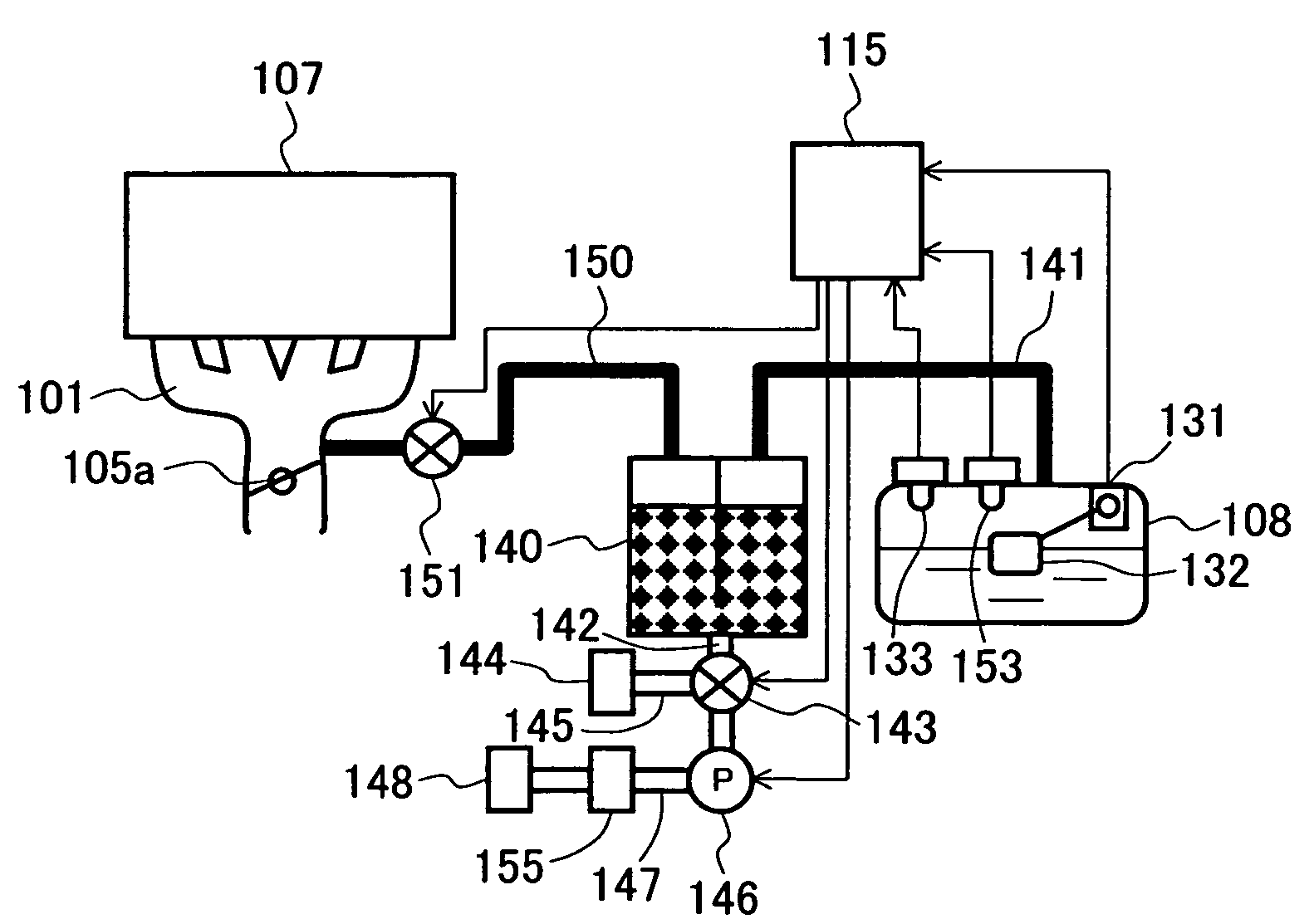
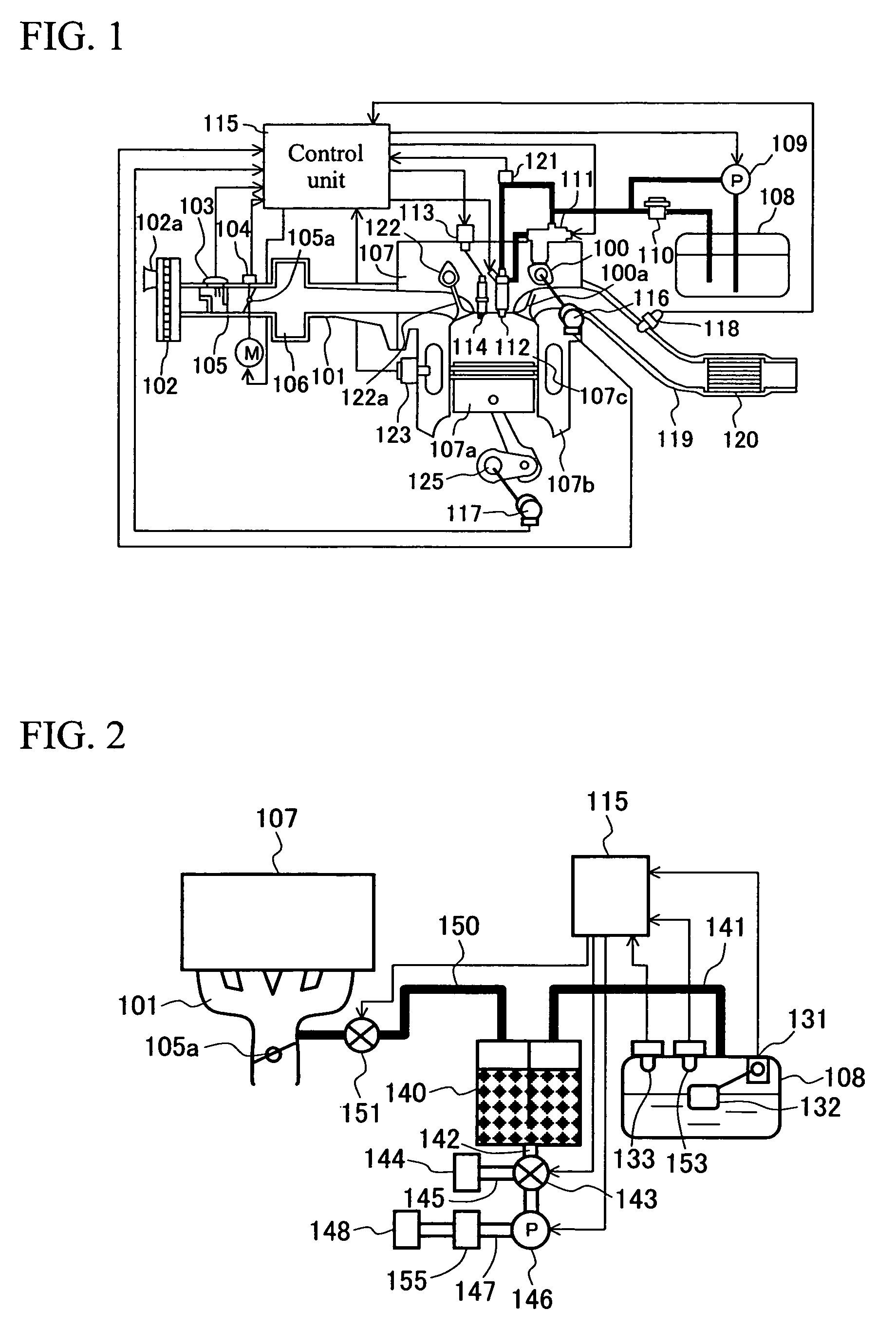
[0060]An in-cylinder injection internal combustion engine 107 includes a cylinder body 107b. The cylinder body 107b includes a plurality of combustion chambers 107c (one of them is shown in FIG. 1). Each combustion chamber 107c is equipped with an injector 112, which provides fuel injection.

[0061]Intake air, which is introduced into the combustion chamber 107c of the internal combustion engine 107, is acquired via an inlet 102a of an air cleaner 102. The intake air then passes through an air flow sensor 103, which is one of a plurality of operating status measurement means of the internal combustion engine 107, passes through a throttle body 105, which houses an electrically controlled throttle valve 105a for intake ai...


PUM


Abstract

Pressure detection means detects the pressure of an evaporation purge system that includes a fuel tank and a communicating tube, which connects a canister for adsorbing and retaining fuel vapor to an intake pipe. Shutout means shuts out the evaporation purge system from atmospheric air. A pump is driven for pressurization or depressurization purposes while the shutout means shuts out the evaporation purge system from atmospheric air. The pump is stopped when the pressure detected by the pressure detection means reaches a predetermined level. A leak judgment is formulated in accordance with pump drive time and a pressure change after pump stoppage.

Description

TECHNICAL FIELD[0001]The present invention relates to an evaporation leak diagnostic device and method for detecting a fuel vapor leak that may occur in a fuel tank of a gasoline engine mounted automobile or other similar vehicle and to an internal combustion engine control device.BACKGROUND ART[0002]Means (negative pressure method) for judging a leak in accordance with pressure changes occurring when an evaporation purge system is placed under negative pressure is well known as a conventional technology for detecting a leak from the evaporation purge system for a fuel tank of an automobile or other vehicle (e.g., Japanese Patent JP-B 2741698 and Japanese Patent JP-A 189825 / 1995).[0003]However, the use of the negative pressure method has not provided an adequate diagnosis frequency in the market. One reason is that the negative pressure is insufficient during a high-load operation. To solve this problem, a method for installing a pump in a purge line between a canister and intake pi...

Claims


Application Information

Patent Timeline
Patent Type & Authority Patents(United States)
IPC IPC(8): F02M33/02F02M1/00F02B75/12F02M25/08
CPCF02M25/0809F02M25/0818F02B2075/125F02D2200/0612Y02T10/123Y02T10/12
Inventor IIHOSHI, YOICHINAKAGAWA, SHINJIHORI, TOSHIOHIKICHI, AKIRA
Owner HITACHI LTD
Why Eureka
Try Eureka