Apparatus and method for controlling internal combustion engine

一种控制设备、内燃机的技术,应用在机械设备、内燃机测试、内燃活塞发动机等方向,能够解决不能提高发动机起动性能等问题

Inactive Publication Date: 2008-02-20
TOYOTA JIDOSHA KK
View PDF1 Cites 15 Cited by
  • Summary
  • Abstract
  • Description
  • Claims
  • Application Information

AI Technical Summary

Problems solved by technology

Therefore, the first fuel injection and ignition cannot be performed at the proper timing (crank angle) after starting the engine
Therefore, the starting performance of the engine cannot be improved

Method used


Image

  • Apparatus and method for controlling internal combustion engine
  • Apparatus and method for controlling internal combustion engine
  • Apparatus and method for controlling internal combustion engine

Examples


Embodiment Construction

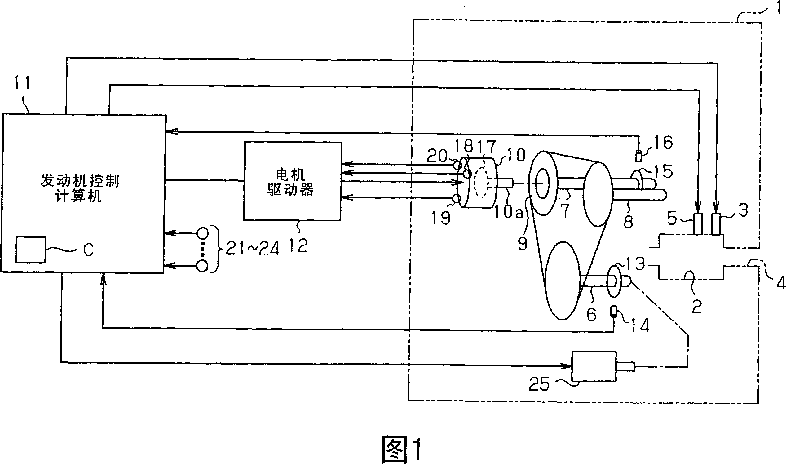
[0036] An automotive multi-cylinder engine 1 according to a preferred embodiment of the present invention will now be described with reference to FIGS. 1 to 22 .

[0037] As shown in FIG. 1 , an engine 1 has combustion chambers 2 (only one is shown) into which fuel is injected by a fuel injection valve 3 in each combustion chamber 2 . Furthermore, air is introduced into each combustion chamber 2 from an intake passage 4 . The air-fuel mixture in each combustion chamber 2 is ignited by a spark plug 5 . When such an air-fuel mixture is ignited so that the air-fuel mixture burns, the combustion energy drives the engine 1 , in other words, rotates the crankshaft 6 . A starter 25 is connected to the crankshaft 6 . When the engine 1 is started (the engine 1 is cranked), the starter 25 forcibly rotates the crankshaft 6 .

[0038] The rotation of the crankshaft 6 is transmitted to an intake camshaft 7 and an exhaust camshaft 8 . The rotation transmitted from the crankshaft 6 is su...


PUM


Abstract

A variable valve timing mechanism 9 includes an electric motor 10 coupled to an intake camshaft 7. A plurality of rotation sensors 18 to 20 are located about the rotor 17 of the electric motor 10. Each of the sensors 18 to 20 outputs a signal corresponding to induced voltage generated by rotation of the rotor 17. Based on the signals form the rotation sensors 18 to 20, reverse rotation of an engine is detected. A counter C is decremented every time a crank signal is output after the occurrence of reverse rotation is detected. Further, a subtraction value Y is computed that corresponds to a discrepancy between the counter C and the actual crank angle caused by a discrepancy between the actual point in time of the occurrence of reverse rotation and the point in time of the detection of the reverse rotation. The counter C is reduced by the subtraction value Y. As a result, reverse direction of the engine is readily detected without providing a dedicated sensor, and the counter is reliably caused to correspond to the actual crank angle.

Description

technical field [0001] The invention relates to a device and a method for controlling an internal combustion engine. Background technique [0002] In an internal combustion engine such as a motor vehicle engine, the crank angle is obtained based on a crank signal and a cam signal. Fuel injection and ignition are performed based on the crank angle (refer to Japanese Patent Laid-Open Publication No. 8-144825). [0003] As the crankshaft rotates, for example, at every 30° of crank angle, a crankshaft position sensor located near the crankshaft rotor (which is mounted to the crankshaft) outputs a crankshaft signal. The crankshaft rotor is profiled to output crankshaft signals from the crankshaft position sensor at equal time intervals. On the other hand, as the crankshaft rotates, a cam signal is output from a cam position sensor located near the cam rotor (which is attached to the camshaft) every time the camshaft rotates 360° (the crank angle is 720°). The cam rotor is prof...

Claims


Application Information

Patent Timeline
Patent Type & Authority Applications(China)
IPC IPC(8): F02D41/34G01P13/04F02D13/02F02D45/00F02P7/067
CPCF02D41/06F01L2820/042F01L2820/041F01L2001/0537F02D2041/0095F01L13/02G01M15/06F01L1/352Y02T10/46F02D2250/06F01L1/344B60W20/00F02P5/1506F01L2800/03F02D41/009F02D37/02B60W10/06F01L2009/0411Y02T10/40F01L9/22
Inventor 中村宗德
Owner TOYOTA JIDOSHA KK
Why Eureka
Try Eureka