Fuel cell unit

a fuel cell and unit technology, applied in the field of fuel cell units, can solve the problems of small electronic apparatus size, small size formation of electronic apparatus, and inability of fuel cell to adopt the function of the fuel cell unit optimum selection, etc., to achieve the effect of improving power generation performance and starting performan

Inactive Publication Date: 2007-07-26
CANON KK
View PDF8 Cites 16 Cited by
  • Summary
  • Abstract
  • Description
  • Claims
  • Application Information

AI Technical Summary

Benefits of technology

[0009]An object of the present invention is to provide a fuel cell in which variation in the moistened state over an entire surface of the polymer electrolyte membrane is reduced to thereby achieve improvement in power generation performance and starting performance.

Problems solved by technology

However, there are considerable limitations regarding an atmospheric air supply port and a vapor discharge port of the fuel cell from the viewpoint of an artistic design and the inner structure of the apparatus.
When the limitations are imposed on the fuel cell from the viewpoint of the artistic design and the inner structure of the apparatus, it is impossible for the fuel cell to adopt an optimum selection in terms of a function of the fuel cell unit.
On the other hand, in the fuel cell as disclosed by U.S. Pat. No. 5,514,486, the external appearance and structure of the fuel cell are optimized in favor of the fuel cell unit, but this disturbs the external appearance design and small-sized formation of the electronic apparatus.

Method used


Image

  • Fuel cell unit
  • Fuel cell unit
  • Fuel cell unit

Examples


first embodiment

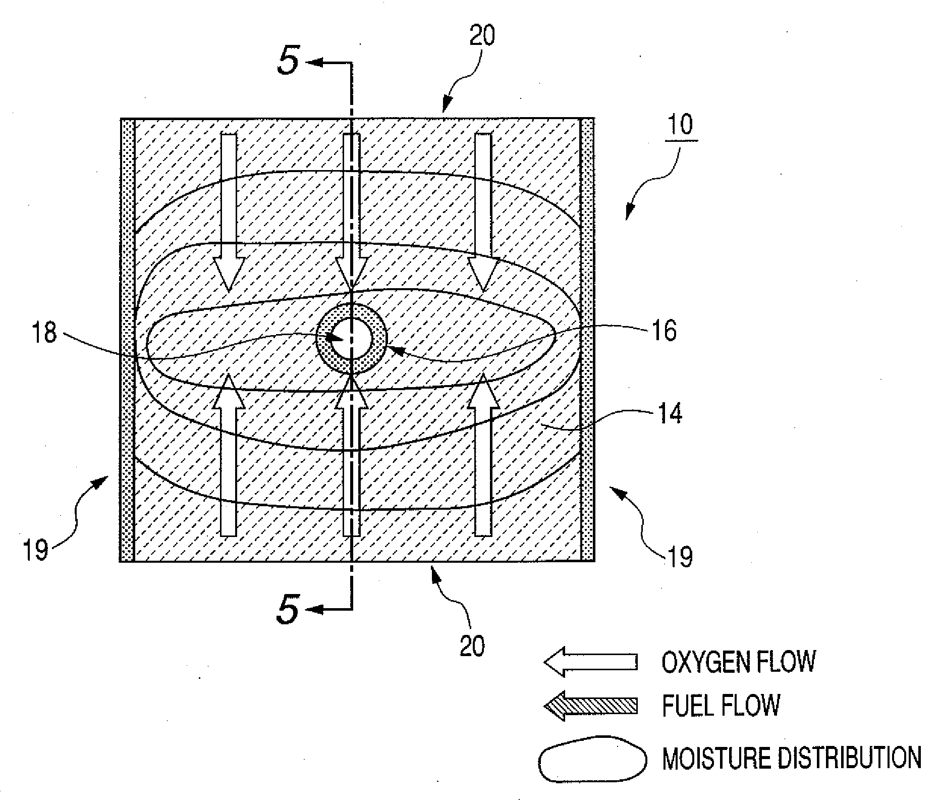
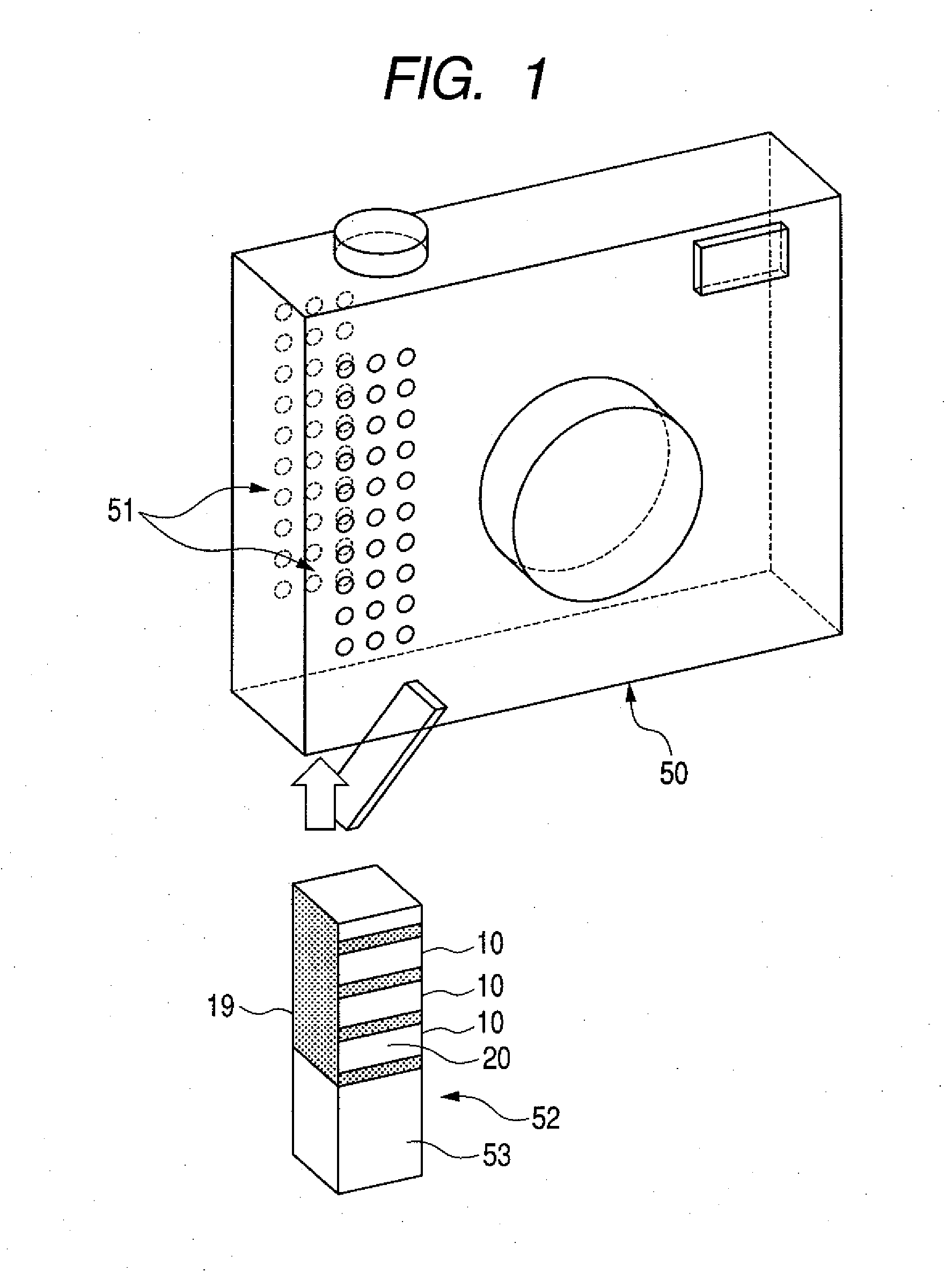
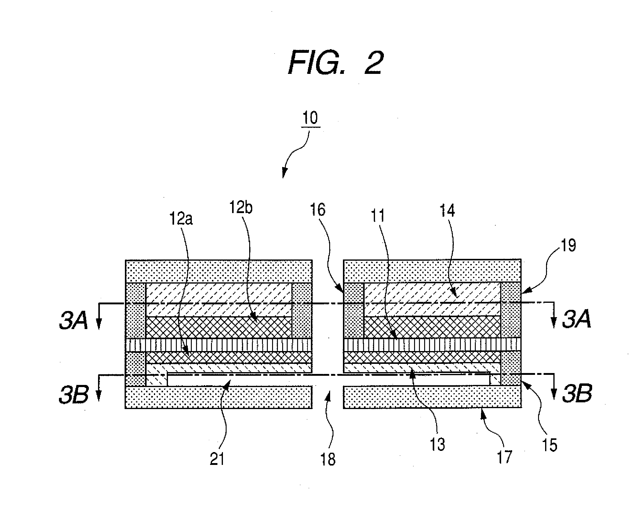
[0029]FIG. 1 is an explanatory view of a constitution of a small electronic apparatus to which a fuel cell according to a first embodiment of the present invention is incorporated; FIG. 2 is an explanatory vertical sectional view illustrating a structure of a fuel cell unit; and FIGS. 3A and 3B are explanatory horizontal sectional views of the fuel cell unit of FIG. 2. FIGS. 4A and 4B are explanatory views illustrating hydrogen gas flow and oxygen flow in the fuel cell unit; and FIG. 5 is an explanatory view illustrating the state of electric power generation using a polymer electrolyte membrane. FIGS. 3A and 4A are horizontal sectional view taken in the line 3A-3A of FIG. 2, and 3B and 4B are horizontal sectional view taken in the line 3B-3B of FIG. 2.

[0030]FIG. 1 is the explanatory view showing the constitution of the small electronic apparatus into which the fuel cell according to this embodiment is incorporated.

[0031]As shown in FIG. 1, the fuel cell 52 of this embodiment can be...

second embodiment

[0056]FIGS. 9A, 9B and 9C are sectional views of a fuel cell unit according to this embodiment. FIG. 9A is a sectional view taken in the same manner as in FIG. 2. FIGS. 9B and 9C are sectional views taken in the same manner as in FIGS. 3A and 3B.

[0057]As shown in FIGS. 9A, 9B and 9C, in this embodiment, the fuel cell unit has a single opening. In this embodiment, the region having a low fuel diffusion resistance is formed in the vicinity of a region which is in point symmetry in the fuel diffusion layer with respect to a region in the fuel diffusion layer existing in the same plane as the opening. Further, the longest segment that can exist in the region having a fuel diffusion resistance of B and that is parallel to the interface between the polymer electrode membrane and the catalyst layer and parallel to the opening is longer than the segment that is perpendicular to the opening and parallel to the interface.

[0058]When forming the groove 21 in the fuel flow field plate 13 as the ...

third embodiment

[0062]In this embodiment, each fuel flow field plate of the fuel cell unit stack has a fuel supply port for introducing fuel and fuel discharge ports for discharging fuel. As shown in FIGS. 10A, 10B and 10C, the fuel flow field plate 13 of this embodiment has a fuel supply port for discharging fuel from the fuel flow path 18 to the fuel flow field plate 13, and a fuel discharge port 54 for discharging fuel from the fuel flow field plate 13 to another fuel cell unit. As shown in FIGS. 10A, 10B and 10C, as in the first embodiment, water is likely to be generated in the region of the oxygen flow field plate 14 containing a symmetry point and parallel to the opening 20. In view of this, a region having a low diffusion coefficient is formed in the region of the fuel flow field plate 13 containing the symmetry point and parallel to the opening 20.

[0063]As shown in FIGS. 10A, 10B and 10C, it is desirable to form the fuel flow path 18 in the vicinity of one end of the region having a low di...


PUM

PropertyMeasurementUnit
thicknessaaaaaaaaaa
thicknessaaaaaaaaaa
porosityaaaaaaaaaa

Abstract

The present invention provides a fuel cell unit having a structure in which vapor is efficiently diffused in a fuel diffusion layer through a region having a reduced diffusion resistance, so that vapor is spread to every corner in a direction along an opening, thereby reducing variation in wetness of a polymer electrolyte membrane. As a result, as compared with a case where there is no region having a reduced diffusion resistance, a proper moistened state is maintained over a wider range of the polymer electrolyte membrane, thereby making it possible to enhance hydrogen ion transfer ability of the polymer electrolyte membrane as a whole.

Description

BACKGROUND OF THE INVENTION[0001]1. Field of the Invention[0002]The present invention relates to a fuel cell unit which effects reaction between hydrogen gas and oxygen in an atmosphere by using a polymer electrolyte membrane capable of moving hydrogen ions in a moistened state, and more specifically, to a technique for securing a proper moistened state throughout the polymer electrolyte membrane.[0003]2. Related Background Art[0004]A polymer electrolyte membrane moving hydrogen ions in a moistened state has been put into practical use, and there has been proposed a fuel cell which effects reaction between hydrogen gas and oxygen in the atmosphere by using a polymer electrolyte membrane. In a fuel cell of this type, fuel cell units each composed of a fuel diffusion layer arranged on one side of a polymer electrolyte membrane and an oxygen diffusion layer arranged on the other side of the membrane are stacked together, and a separator or the like is provided each between the fuel dif...

Claims


Application Information

Patent Timeline
Patent Type & Authority Applications(United States)
IPC IPC(8): H01M4/94H01M8/02
CPCH01M8/023H01M8/0247Y02E60/521H01M8/1002H01M2008/1095H01M8/04126H01M8/1007Y02E60/50
Inventor MOGI, SATOSHISHIBATA, MASAAKI
Owner CANON KK
Why Eureka
Try Eureka