Single-thimble acceleration ejection mechanism of injection mold

A technology for injection molds and accelerating tops, which is applied in the field of injection molds and can solve problems such as reduced production efficiency, shutdown of injection molding machines, and failure of products to fall off automatically

Inactive Publication Date: 2015-09-30
浙江艾彼科技股份有限公司
View PDF2 Cites 0 Cited by
  • Summary
  • Abstract
  • Description
  • Claims
  • Application Information

AI Technical Summary

Problems solved by technology

[0002] Injection molds are used to produce plastic products, such as automobile decoration parts, etc. There are many ribs, feet and holes on the back of such products. During the mold design process, the cores of these ribs, feet and holes are often formed by ejector pins ( The ejector pin) is directly replaced, that is, th

Method used


Image

  • Single-thimble acceleration ejection mechanism of injection mold
  • Single-thimble acceleration ejection mechanism of injection mold

Examples


Embodiment Construction

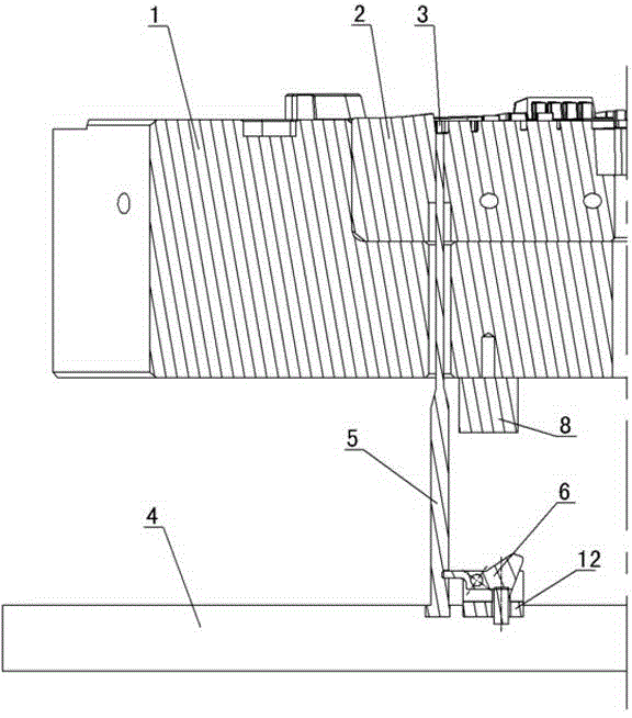
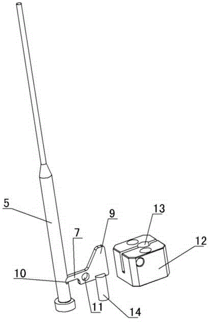
[0009] The invention relates to an injection mold single thimble accelerated ejection mechanism, such as figure 1 , figure 2 As shown, it includes mold movable template 1, movable mold insert 2 is installed in the movable template, product cavity is set on the movable mold insert, thimble plate 4 is located under the movable template, thimble plate is connected with thimble 5, and thimble 5 passes through the movable template 1 and the movable mold insert 2 are matched with the rib hole part 3 of the product cavity, and a seesaw 6 is arranged on the ejector plate 4 on the side of the thimble, and the head 7 of the seesaw 6 is connected to the thimble 5, under the movable template 1 Block 8 is installed, when the thimble plate tops, the afterbody 9 of seesaw touches block 8 to make seesaw 6 tilt. The main feature of this scheme is that a seesaw 6 is set on the thimble plate 4, the head 7 of the seesaw 6 is connected to the thimble 5, and a stopper 8 is installed under the mov...


PUM


Abstract

The invention discloses a single-thimble acceleration ejection mechanism of an injection mold. The mechanism comprises a mold movable template, wherein a movable mold insert is mounted in the movable template, and is provided with a product mold cavity; a thimble plate is arranged below the movable template, and is connected with a thimble; the thimble penetrates through the movable template and the movable mold insert to fit a rib hole part of the product mold cavity; a turning plate is arranged on the thimble plate at one side of the thimble; the head part of the turning plate is connected with the thimble; a stopper is mounted below the movable template; when the thimble plate is upwards ejected, the tail part of the turning plate is touched with the stopper to upwards turn the turning plate so as to drive the thimble to be accelerated and ejected; the rib hole part of the product and the thimble are ejected out firstly; the thimble plate is continuously upwards ejected to drive other thimbles to eject the product outside the mold; and the mold release of the product is smooth.

Description

technical field [0001] The invention relates to an accelerated ejection mechanism for a single thimble of an injection mold, belonging to the field of injection molds. Background technique [0002] Injection molds are used to produce plastic products, such as automobile decoration parts, etc. There are many ribs, feet and holes on the back of such products. During the mold design process, the cores of these ribs, feet and holes are often formed by ejector pins ( The ejector pin) is directly replaced, that is, the product is connected to the ejector pin. Therefore, when the ejector pin is ejected and the product is demoulded, the product sometimes sticks to the ejector pin, causing the product to fail to fall off automatically, or even causing the mold to be stuck, and the injection molding machine to stop, reducing the Productivity. Contents of the invention [0003] The purpose of the present invention is to overcome the disadvantages of the prior art, and provide a sing...

Claims


Application Information

Patent Timeline
IPC IPC(8): B29C45/40
CPCB29C45/401
Inventor 何建军
Owner 浙江艾彼科技股份有限公司
Why Eureka
Try Eureka