Demolding unit and demolding method

A demoulding and unit technology, applied in the direction of mold handling equipment, manufacturing tools, metal processing equipment, etc., can solve the problems of heavy quality, low production efficiency, and many specifications

Pending Publication Date: 2020-02-28
CERI TECH +1
View PDF0 Cites 10 Cited by
  • Summary
  • Abstract
  • Description
  • Claims
  • Application Information

AI Technical Summary

Problems solved by technology

However, due to the large size, multiple specifications and heavy weight of the induction rod and the steel ingot mold, the labor intensity during operation is high, the production efficiency is low, and the induction rod is easy to fall during the demoulding process, and even the driving decoupling and the steel ingot slippage may occur. Accidents and other accidents have great potential safety hazards
In addition, in the prior art, the demoulding of the induction rod also uses the ejection hydraulic cylinder to provide thrust from the tail of the steel ingot mold to complete the separation of the steel ingot mold and the induction rod, but this method cannot completely separate the steel ingot mold from the induction rod. Moreover, due to the large size of the steel ingot mold, the placement position is completely completed by the driving assistance, without the centering and adjustment functions, which will cause the thrust of the hydraulic cylinder to be unable to accurately act on the center position of the tail of the steel ingot mold, which will affect the demoulding efficiency and quality. Applying thrust under eccentric conditions will cause a certain degree of damage to the inner wall of the ingot mold
[0005] Aiming at the low demoulding efficiency of the induction rod in the related technology, there are potential safety hazards, and the demoulding process will cause damage to the ingot mold, there is no effective solution yet

Method used


Image

  • Demolding unit and demolding method
  • Demolding unit and demolding method
  • Demolding unit and demolding method

Examples


Embodiment 1

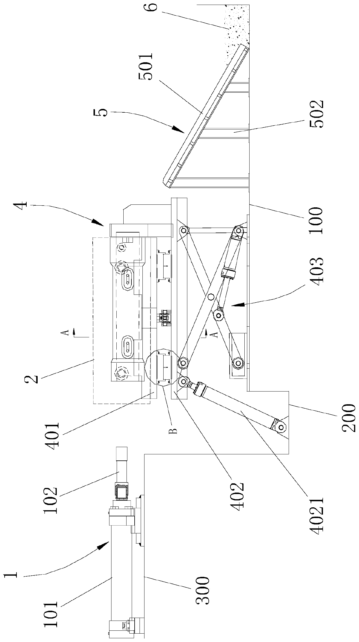
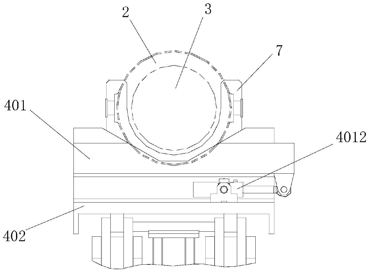
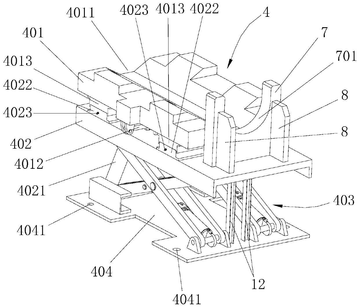
[0084] Such as Figure 1 to Figure 8 As shown, the present invention provides a demoulding unit, which includes a ejector device 1, a multi-degree-of-freedom lifting and turning device 4 and a guide device 5, and the ejector device 1 is used for the induction rod 3 in the steel ingot mold 2 Apply a thrust to separate the outer wall of the induction rod 3 from the inner wall of the ingot mold 2; the multi-degree-of-freedom lifting and turning device 4 is used to adjust the centering position and inclination angle of the induction rod 3; the guide device 5 is used to connect with the ingot mold 2 The separated sensing rod 3 is output to the receiving buffer 6 . Wherein: the multi-degree-of-freedom lifting and turning device 4 comprises a mobile platform 401, a turning platform 402 and a lifting mechanism 403, the moving platform 401 and the turning platform 402 are rectangular flat structures arranged along the horizontal direction, and the bottom of the lifting mechanism 403 is...

Embodiment 2

[0118] Such as figure 1 , Figure 8 As shown, the invention provides a kind of demoulding method, and this demoulding method comprises the steps:

[0119] Step S1: Fix the position of the ejector device 1, the multi-degree-of-freedom lifting and turning device 4 and the guiding device 5. The ejecting device 1 and the guiding device 5 are respectively located on both sides of the multi-degree-of-freedom lifting and turning device 4, and the guiding device 5 is located near the On the side of the receiving buffer zone 6, the ejector device 1 is located away from the side of the receiving buffer zone 6, and the lifting mechanism 403 of the multi-degree-of-freedom lifting and turning device 4 is lowered to the lowest position;

[0120] Wherein, the lowest position of the lifting mechanism 403 can be adjusted according to the specifications of the largest steel ingot mold 2, so as to ensure that the largest steel ingot mold 2 can be completely separated from the induction rod 3 in...


PUM


Abstract

The invention provides a demolding unit and a demolding method. The demolding unit comprises a multi-freedom-degree lifting and overturning device, an ejecting device and a guide device; the multi-freedom-degree lifting and overturning device comprises a moving platform, an overturning platform and a lifting mechanism; the top of the lifting mechanism is connected with the overturning platform ina pivoting manner; the bottom of the overturning platform is provided with a first driving device used for pushing the overturning platform to realize overturning; the moving platform can be movably arranged at the top of the overturning platform; the top of the moving platform is fixedly provided with a steel ingot mold so that the moving direction of the moving platform is perpendicular to the axial direction of a sensing rod; the ejecting device and the guide device are correspondingly arranged at the two sides of the multi-freedom-degree lifting and overturning device; the ejecting deviceleans against the end part of the sensing rod; thrust is applied from a thrust applying end of the steel ingot mold to the sensing rod; and the guide device is connected between the steel ingot mold and a receiving buffer region. The demolding unit provided by the invention solves the technical problems that the sensing rod is relatively low in demolding efficiency and causes potential safety hazards and the steel ingot mold may be damaged in a demolding process.

Description

technical field [0001] The invention relates to the technical field of metallurgical equipment, and further relates to a demoulding unit and a demoulding method, in particular to a demoulding unit and a demoulding method applicable to multi-standard induction rods. Background technique [0002] Vacuum induction melting technology is currently the induction heating technology with the highest heating efficiency and the fastest speed for metal materials, which has the characteristics of low energy consumption, energy saving and environmental protection. [0003] Vacuum induction melting technology is specifically as follows: put solid metal raw materials into a crucible wound by a coil, the induced electromotive force of the induction coil causes eddy currents to be generated inside the metal charge, and the heat generated makes the metal melt from solid to liquid, thus completing The smelting of metals achieves the purpose of refining by adjusting the smelting temperature and...

Claims


Application Information

Patent Timeline
Patent Type & Authority Applications(China)
IPC IPC(8): B22D29/04B22D33/02
CPCB22D29/04B22D33/02
Inventor 谢宇林怀峰孙亮
Owner CERI TECH
Why Eureka
Try Eureka