
Magnetic type floor drain

A magnetic suction, floor drain technology, applied in waterway systems, drainage structures, water supply devices, etc., can solve problems such as inability to meet, hidden dangers in use, and difficult built-in assembly, and achieve the effect of simple structure, convenient assembly and connection, and fewer accessories.

Active Publication Date: 2015-09-30
冯涛 +2
View PDF9 Cites 8 Cited by
  • Summary
  • Abstract
  • Description
  • Claims
  • Application Information

AI Technical Summary

Problems solved by technology

[0002] Invention patent CN2013103905824 discloses a magnetic straight-through combined floor drain. This patent overcomes the problem that the suction force of the original magnetic floor drain decreases as the sealing cover moves down when draining water, and can effectively avoid the phenomenon of sealing cover reset failure. , but the above structure has the problems of many accessories, complicated structure and difficult built-in assembly. At the same time, because the magnetic suction structure is set in the middle of the floor drain body, it is easy to absorb magnetic impurities during the drainage process and cause blockage. The most important thing is Its drainage is still through the downward movement of the sealing cover to create a gap between the floor drain body and the drainage. This drainage method still cannot meet the actual needs of large water drainage in a short and medium time, resulting in certain safety hazards in use.

Method used


Image

  • Magnetic type floor drain
  • Magnetic type floor drain
  • Magnetic type floor drain

Examples


Embodiment Construction

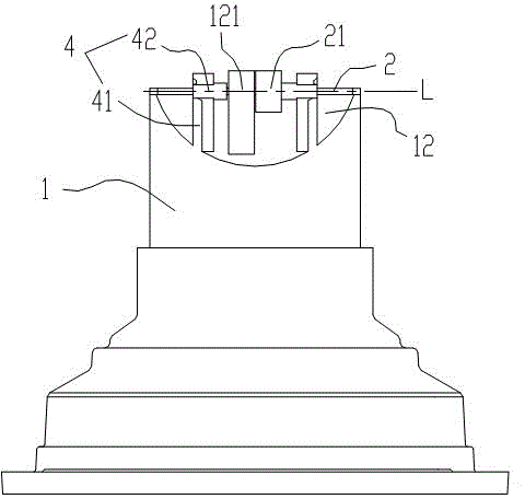
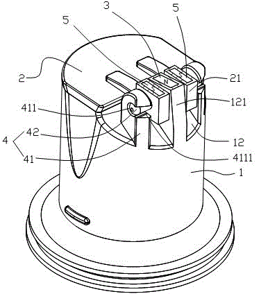
[0028] Such as Figure 1-3 As shown, a magnetic floor drain includes a floor drain body 1 and a sealing cover 2 , and a straight water outlet 11 is provided at the lower part of the floor drain body 1 .

[0029] The water outlet 11 is provided with a positioning surface 12 on one side, and at least certain magnetic blocks 3 are installed on the positioning surface 12, and each fixed magnetic block 3 is arranged and arranged at intervals, and the fixed magnetic block 3 provided in this embodiment is one , in actual use, two or more fixed magnet blocks 3 can be set according to the size of the sealing cover 2 . One side of the sealing cover 2 is movably connected with the positioning surface 12 of the floor drain body 1 through the hinge structure 4, and the sealing cover 2 is provided with a moving magnet block 5 on its hinged side at the same time, and the centers of the moving magnet block 5 and the fixed magnet block 3 are uniform. Located on the axis L of the hinged struct...


PUM


Abstract

The invention discloses a magnetic type floor drain which comprises a floor drain body and a sealing cover. The lower portion of the floor drain body is provided with a straight-through water outlet. A positioning face is arranged on one side of the water outlet and provided with at least one fixed magnetic block. The fixed magnetic blocks are arranged at intervals. One side of the sealing cover is movably connected with the positioning face of the floor drain body through a hinge structure. The hinged side of the sealing cover is provided with movable magnetic blocks. The centers of the movable magnetic blocks and the fixed magnetic blocks are located on the axis of the hinge structure. The movable magnetic blocks and the fixed magnetic blocks generate reset force by means of the principle that different magnetic poles are attracted and the same magnetic poles are repellent, and therefore the sealing cover tightly seals the water outlet. On the premise of ensuring that the reset force of the sealing cover is not reduced during drainage, adaptive drainage of the floor drain is achieved, and the magnetic type floor drain has the advantages of being simple and practical in structure, being provided with a small number of accessories and being easy and convenient to assemble.

Description

technical field [0001] The invention relates to a floor drain, in particular to a magnetic suction type floor drain. Background technique [0002] Invention patent CN2013103905824 discloses a magnetic straight-through combined floor drain. This patent overcomes the problem that the suction force of the original magnetic floor drain decreases as the sealing cover moves down when draining water, and can effectively avoid the phenomenon of sealing cover reset failure. , but the above structure has the problems of many accessories, complicated structure and difficult built-in assembly. At the same time, because the magnetic suction structure is set in the middle of the floor drain body, it is easy to absorb magnetic impurities during the drainage process and cause blockage. The most important thing is Its drainage is still through the downward movement of the sealing cover to form a gap with the floor drain body for drainage. This drainage method still cannot meet the actual nee...

Claims


Application Information

Patent Timeline
Patent Type & Authority Applications(China)
IPC IPC(8): E03F5/04
Inventor 张金荣
Owner 冯涛
Learn More