
Pavement pit detecting method based on vehicular binocular vision

A technology of binocular vision and detection method, which is applied in the direction of measuring devices, instruments, and optical devices, etc., and can solve the problem that the spatial information of road potholes cannot be measured.

Inactive Publication Date: 2015-10-07
SUZHOU UNIV OF SCI & TECH
View PDF12 Cites 12 Cited by
  • Summary
  • Abstract
  • Description
  • Claims
  • Application Information

AI Technical Summary

Problems solved by technology

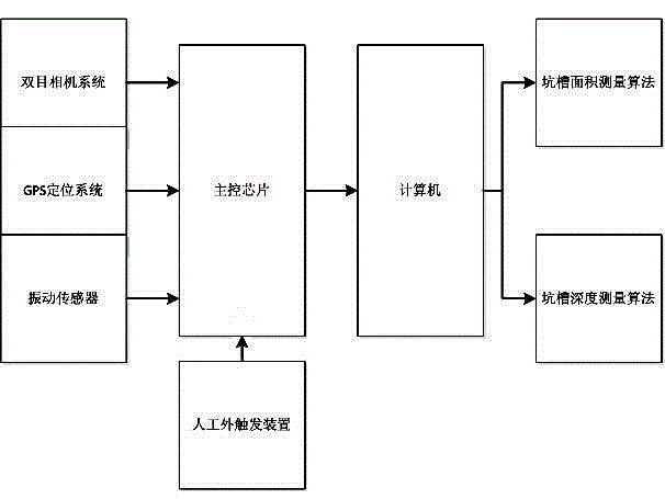
[0004] In order to solve the defect that the traditional method cannot measure the spatial information of road potholes, the present invention combines GPS, binocular cameras, vibration sensors and other hardware devices, and uses the vehicle-mounted method to locate the position of the potholes, collect images of the potholes, and use The image algorithm calculates the area and depth information of the pit

Method used


Image

  • Pavement pit detecting method based on vehicular binocular vision
  • Pavement pit detecting method based on vehicular binocular vision
  • Pavement pit detecting method based on vehicular binocular vision

Examples


Embodiment Construction

[0036] The present invention will be described in detail below with reference to the accompanying drawings and in combination with embodiments.

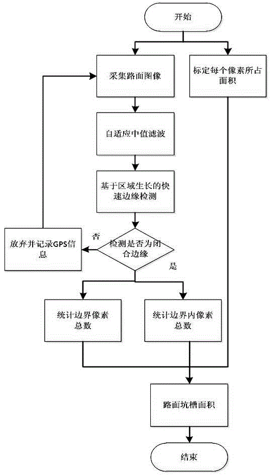
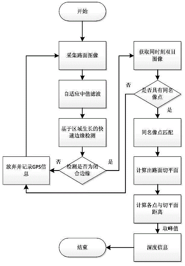
[0037] refer to figure 1 As shown, a road surface pothole detection method based on vehicle-mounted binocular vision, the hardware based on the method includes a main control chip, and the main control chip is respectively connected with a binocular camera system, a GPS positioning system, a vibration sensor, and an artificial external trigger. The device and the computer are characterized in that the binocular camera system is installed on the roof of the vehicle to collect road images, the GPS positioning system is fixed on the roof of the vehicle together with the binocular camera system, and the vibration sensor is fixed on the vehicle instrument In the disk, the manual external trigger device is fixed on the co-pilot panel, and the computer calculates the area of ​​road surface pits and the depth of road surface pits according t...


PUM


Abstract

The invention provides a pavement pit detecting method based on vehicular binocular vision. The method singles out a pavement pit by selecting a reasonable threshold of vibration sampling information of a vibration sensor, gives positional information of the pavement pit in combination with GPS information, and records GPS information by using a key manual external trigging device when wheels run over the pavement pit. A binocular camera system samples a tested pavement and outputs an image to a computer. After acquiring the image of the pavement pit, the computer performs preprocessing and an image processing algorithm on the image so as to obtain the area and depth information of the pavement pit. The method may position the pavement pit, optimizes the conventional image processing algorithm, and may accurately achieve a pavement pit area and depth computing function.

Description

technical field [0001] The invention relates to the field of road detection and image processing, in particular to a detection method for measuring the position, area and depth information of road potholes based on binocular vision and using an image processing algorithm. Background technique [0002] In recent years, economic development has led to an increase in the number of vehicles. With the accumulated wear and tear of the road surface, the appearance of potholes is inevitable. Therefore, the importance of road pothole detection for vehicle driving is self-evident. Pothole inspection is an important part of pavement quality inspection. The development of digital image processing technology makes traditional pavement inspection work more intelligent and mechanized. [0003] However, pavement potholes are a special form of pavement damage. Traditional road surface measurement methods, such as bump accumulators and laser rangefinders, can only obtain the curve of the long...

Claims


Application Information

Patent Timeline
Patent Type & Authority Applications(China)
IPC IPC(8): G01D21/02G01B11/22G01B11/28
Inventor 杨会玲王军孙慧婷张丰梁王磊
Owner SUZHOU UNIV OF SCI & TECH
Learn More