Electric weather shed

An awning and electric technology, applied in the field of awnings, can solve the problems of difficult operation and inability to close the awning, and achieve the effect of strong practicability, simple structure, and smooth movement

Active Publication Date: 2015-10-14
梁生炜
View PDF9 Cites 3 Cited by
  • Summary
  • Abstract
  • Description
  • Claims
  • Application Information

AI Technical Summary

Problems solved by technology

[0004] The invention provides an electric awning, the main purpose of which is to overcome the defect that the existing awning cannot be closed and is not easy to operate

Method used


Image

  • Electric weather shed
  • Electric weather shed
  • Electric weather shed

Examples


Embodiment 1

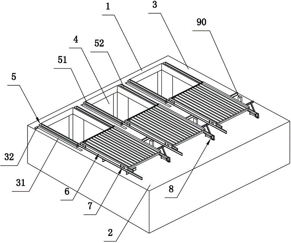
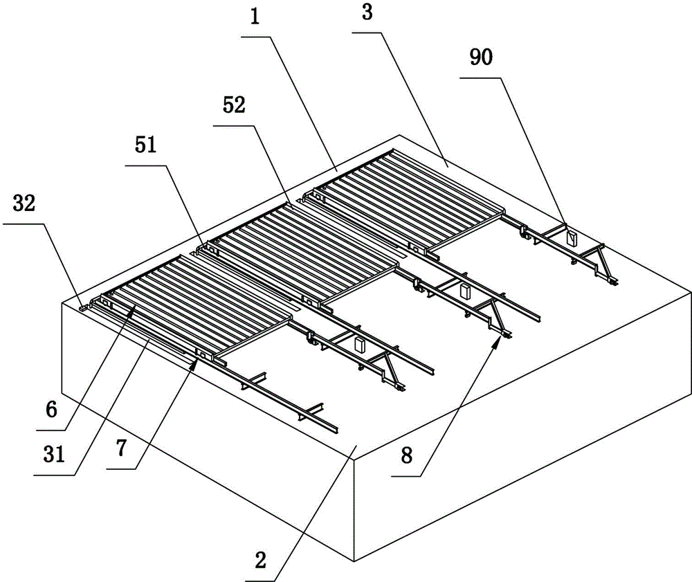
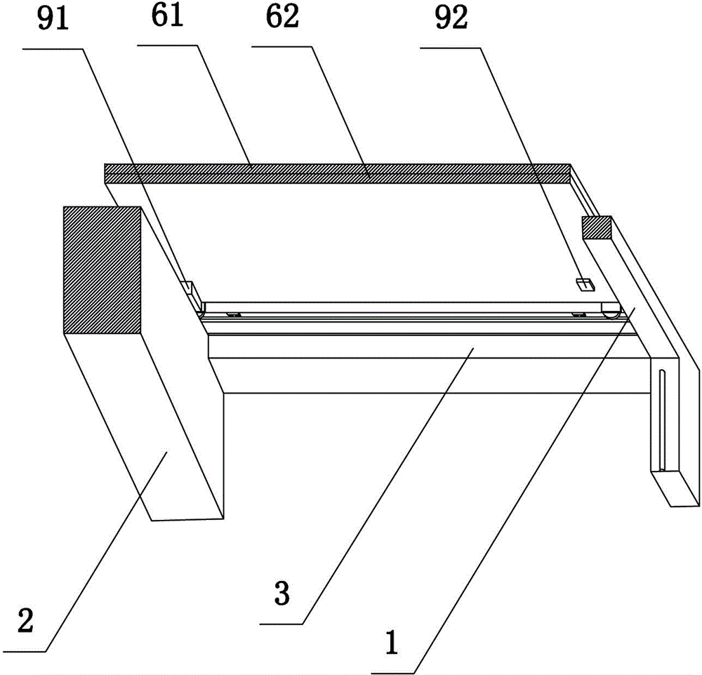
[0036] refer to figure 1 , figure 2 , image 3 and Figure 4. An electric awning comprises at least one roof installed on a semi-open roof, wherein the semi-open roof includes a transverse support frame 1 and a closing part 2, and the transverse support frame 1 and the closing part 2 pass through a plurality of Two longitudinal support frames 3 distributed at equal intervals are connected, and an open part 4 is provided between two adjacent longitudinal support frames 3, and a ceiling is installed above the open part 4. The ceiling includes a rail mechanism 5 and a baffle mechanism 6 whose size can completely cover the opening 4, wherein the rail mechanism 5 includes an I-shaped left longitudinal rail 51 and an I-shaped right longitudinal rail 52, and the left longitudinal rail 51 and the right longitudinal rail 52 are respectively installed on the longitudinal support frame 3 on the left and right sides of the open part 4 and extend to the upper side of the closed part 2...

Embodiment 2

[0044] refer to image 3 , Figure 5 , Figure 6 and Figure 7 . The difference between the second embodiment and the first embodiment is that the guide components are different. The guide assembly 73 of the second embodiment includes two spaced left locking blocks 731 and two spaced right locking blocks, each left locking block 731 is fixedly connected to the left side of the baffle mechanism 6 at one end, and the other is One end is clamped between the upper part and the lower part of the I-shaped left longitudinal track 51, and the uniform end of each right clamping block is fixedly connected with the right side of the baffle plate mechanism 6, and the other end is clamped on the top of the I-shaped right longitudinal track 52 and between the lower part. By arranging the left clamping block and the right clamping block, the left and right sides of the baffle mechanism are respectively clamped on the I-shaped left longitudinal track and the I-shaped right longitudinal t...


PUM


Abstract

An electric weather shed comprises at least one ceiling installed on a semi-open roof; each ceiling comprises a track mechanism and a baffle plate mechanism which can completely cover an open portion; each track mechanism comprises a left longitudinal track and a right longitudinal track which are symmetrical and parallel to each other; each left longitudinal track and the corresponding right longitudinal track are respectively installed on longitudinal supporting frames at left and right sides of the corresponding open portion and extend to an upper side of an enclosed portion; each baffle plate mechanism is slidably installed on the corresponding track mechanism via a walking guiding mechanism; and each baffle plate mechanism can move or stop back and forth over the corresponding open portion and over the enclosed portion along the corresponding track mechanism. According to the apparatus, residents can control each baffle plate mechanism to move to any position over the corresponding open portion or the enclosed portion to shield or enjoy sunlight, rain, dew and ice according to self demand, the electric weather shed is simple and rapid in operation and has heat insulation and leakproof effects, and high quality lives of the residents are substantially satisfied.

Description

technical field [0001] The invention relates to an awning, in particular to an electric awning. Background technique [0002] The awning is mainly used in residences with yards or large-area balconies. Most of the yards or large-area balconies have no shelters above them, which can make it easier for residents to get sunlight, to facilitate residents to dry clothes, plant flowers, etc., but it also brings some Problems, such as: sun exposure, no heat insulation, no rainproof, no leakproof, etc., so many residents will install awnings for their residences. [0003] Most of the existing awnings are fixed or can be manually disassembled or stretched, but neither disassembly nor stretching is an operation that residents can easily complete, which brings a lot of inconvenience to the lives of residents. Contents of the invention [0004] The invention provides an electric awning, the main purpose of which is to overcome the defect that the existing awning cannot be closed and ...

Claims


Application Information

Patent Timeline
Patent Type & Authority Applications(China)
IPC IPC(8): E04F10/08
Inventor 梁生炜
Owner 梁生炜
Why Eureka
Try Eureka