
A ceiling keel and a combined three-dimensional ceiling composed of it

A ceiling and keel technology, applied in the field of decoration, can solve the problems of inconvenient disassembly and assembly and cannot be reused, such as temples, airport terminals, department store halls or exhibition halls, etc., to achieve simple adjustment and fire prevention. Compatible performance, good decorative effect

Inactive Publication Date: 2015-12-23
黄一帆
View PDF5 Cites 1 Cited by
  • Summary
  • Abstract
  • Description
  • Claims
  • Application Information

AI Technical Summary

Problems solved by technology

Because the main frame adopts an inverted T shape, however, this kind of ceiling is only a flat combination, which is a flat structure without layers, which cannot reflect three-dimensional layers, and is inconvenient to disassemble and assemble. Generally, it cannot be reused.
This structure is only suitable for general office places with simple requirements, but not for places that require three-dimensional layered ceilings, such as temples, airport terminal buildings, department store halls or exhibition halls, etc.
For example, in order to inherit the traditional style, the temple decoration needs an antique ceiling with three-dimensional layering, and the traditional ones are made of wood. It is quite easy to carve layered stripes on the ceiling frame, but its fire performance does not meet the requirements of public places. requirements, wooden materials cannot be used

Method used


Image

  • A ceiling keel and a combined three-dimensional ceiling composed of it
  • A ceiling keel and a combined three-dimensional ceiling composed of it
  • A ceiling keel and a combined three-dimensional ceiling composed of it

Examples


Embodiment Construction

[0031] Typical embodiments of the present invention will be described below.

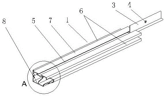
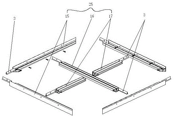
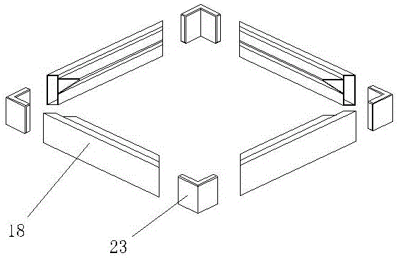
[0032] see Figure 1~Figure 6 , as can be seen from the figure, the ceiling keel 25 includes an aluminum alloy profile 1 with a hollow structure inside, and a connecting fastener 3 that can be buckled on the aluminum alloy profile 1 and can slide. The connecting fastener 3 is an inverted T-shaped structure. There is a mounting hole 4 on the top; the middle part of the top side 6 of the section of the aluminum alloy profile 1 is provided with a convex edge 7 on opposite sides, and the middle part of the convex edge 7 is provided with a back-shaped groove 5 with a top opening, and the groove 5 is connected to the The shape of the fastener 3 is matched, and the outer surface of the aluminum alloy profile 1 is covered with a layer of PVC or leather fabric, and the surface of the PVC or leather fabric has patterns. Multiple connecting fasteners 3 can be provided for longer ceiling keels 25 .

[0033] F...


PUM


Abstract

The invention discloses a ceiling keel and a combined-type stereoscopic ceiling employing same. The ceiling keel comprises an aluminum alloy profile adopting a hollow structure and a connecting clasp capable of being fastened on the aluminum alloy profile and sliding, wherein the connecting clasp adopts an inverted T-shaped structure and a mounting hole is formed in the connecting clasp; a convex edge raised relative to two sides is arranged in the top edge middle of the section of the aluminum alloy profile; a groove shaped like two squares sleeved together is formed in the middle of the convex edge, and the groove of which the top is opened is matched with the connecting clasp in shape; a layer of PVC (polyvinyl chloride) or leather fabric with textures on the surface is wrapped on the outer surface of the aluminum alloy profile; the combined-type stereoscopic ceiling comprises an upper cover plate, a ceiling frame and a keel frame which are sequentially arranged from the top down; the keel frame is formed by splicing the ceiling keel; and the ceiling frame is arranged at the top edge on one side of the convex edge. The ceiling keel and the combined-type stereoscopic ceiling have the following advantages: the installation and the adjustment are simple and convenient; stereoscopic layering is realized and the fire-resistant performance conforms to the requirements of public places; and an excellent decorative effect is achieved to meet the pursuit for high-quality life of modern people.

Description

technical field [0001] The invention relates to the field of decoration, in particular to a ceiling. Background technique [0002] The common ceiling structure mainly consists of several main frames and sub-frames. The main frame is fixed on the upper wall by galvanized iron wires to form a skeleton plane, and gypsum boards and other plates are placed on the skeleton plane to form a ceiling. Because the main frame adopts an inverted T shape, however, this kind of ceiling is only a flat combination, which is a flat plate structure without layers, which cannot reflect three-dimensional layers, and is inconvenient to disassemble and assemble. Generally, it cannot be reused. This structure is only suitable for general office places with simple requirements, but not suitable for places that require three-dimensional layered ceilings, such as temples, airport terminal buildings, department store halls or exhibition halls. For example, in order to inherit the traditional style, th...

Claims


Application Information

Patent Timeline
Patent Type & Authority Patents(China)
IPC IPC(8): E04B9/06E04F13/072E04F13/24
Inventor 黄一帆
Owner 黄一帆
Learn More