Depth of field indication using focus-peaking picture markers

一种原始图像、频率阈值的技术,应用在使用对焦峰值图片标记的景深指示领域,能够解决未给用户提供对焦信息等问题

Active Publication Date: 2015-10-14
PROJECT GIANTS LLC
View PDF4 Cites 2 Cited by
  • Summary
  • Abstract
  • Description
  • Claims
  • Application Information

AI Technical Summary

Problems solved by technology

Occasionally, even the graph showing the focus peaking overlay does not provide the user with as much focus information as desired

Method used


Image

  • Depth of field indication using focus-peaking picture markers
  • Depth of field indication using focus-peaking picture markers
  • Depth of field indication using focus-peaking picture markers

Examples


Embodiment Construction

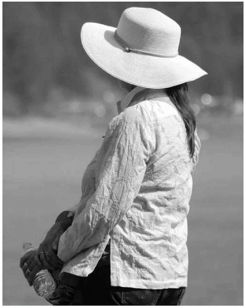
[0018] figure 1 is a block diagram showing substantial portions of an example video waveform monitor according to an embodiment of the present invention. Such as figure 1 As illustrated in , waveform monitor 20 is coupled to and receives input from camera 12 directed at subject 14 . Camera 12 may produce still or moving images. Camera 12 typically includes adjustments for focus and depth of field (DOF) that are controllable by the camera operator, or the adjustments may be controlled automatically. The camera 12 output is input to a waveform monitor 20 . The output from the camera 12 may be gamma corrected or log corrected (log corrected) Y'Cr'Cb or R'G'B components. This correction may take place in the camera 12, modifying the signal from a linear function of the optical input of the camera to a non-linear transfer function to obtain sufficient dynamic range or bit size of the output signal. The commonly used gamma transfer function has been used in television and compu...


PUM


Abstract

A waveform monitor for generating a modified image from an original image includes a measuring system to select luminance frequency values of the original image that are above a first and a second threshold. A modifier changes selected pixels of the original image that fall above the first and second thresholds. In some embodiments these changed pixels are given a false color as color markers to indicate DOF and areas of sharpest focus of the original image. Methods of modifying images in this manner are also described.

Description

[0001] Cross References to Related Applications [0002] This application claims the benefit of U.S. Provisional Application 61 / 975,624, filed April 4, 2014, entitled MULTIPLE FOCUS-PEAKING PICTURE MARKERS ALLOWING DEPTH OF FIELD INDICATION FOR ADJUSTING CAMERA FOCUS, the teachings of which are incorporated by reference and into this article. technical field [0003] The present disclosure relates to a method of displaying information on a monitor, and more particularly, to an apparatus for creating a focus peak false-color overlay simultaneously indicating both the point of sharpest focus and the range of focus or depth of field (DOF) and methods. Background technique [0004] "On-set" or "on-site" video and film productions often require precise camera lens focus / iris adjustments to set the focus area of ​​the image frame and depth of field (DOF) to determine what is in the image content. How much should be in focus. Often, there are artistic reasons to minimize DOF to ...

Claims


Application Information

Patent Timeline
Patent Type & Authority Applications(China)
IPC IPC(8): H04N5/232H04N9/04
CPCH04N17/02G03B13/30H04N5/23212H04N5/23222H04N5/23293H04N23/673H04N23/635H04N23/64
Inventor D.G.贝克
Owner PROJECT GIANTS LLC
Why Eureka
Try Eureka