A terminal shunt connector

A terminal and connector technology, applied in the direction of connection, clamping/spring connection, parts of connection devices, etc., can solve the problems of reducing labor intensity, short service life, reducing wiring efficiency, etc., and achieves easy wiring work , Easy off-line, high construction efficiency

Active Publication Date: 2017-08-15
JIANG MEN TOP ELECTRIC INTELLIGENCE
View PDF11 Cites 1 Cited by
  • Summary
  • Abstract
  • Description
  • Claims
  • Application Information

AI Technical Summary

Problems solved by technology

However, the structures of the existing terminal blocks are varied, and the wiring cannot be completed in one step. It is often necessary to disassemble the terminal block and use bolts, rivets, etc. to connect the wires to the terminal block. Wiring process and reduce the efficiency of wiring, increase labor intensity
And the wiring terminal is equipped with wires, it is necessary to take the wires off the wire from the wiring terminal, and it is necessary to disassemble the wiring terminal again, loosen fixing parts such as bolts, so that the wire is separated from the conductive sheet of the wiring terminal, which is very inconvenient.
Especially when the wiring of existing electrical appliances or electronic components needs to realize the connection of hard wires and flexible wires or different numbers of strands through the cooperation of at least two terminals, it is quite troublesome that these two terminals cannot be connected at one time. A large number of construction sites require wiring, and these cumbersome wiring procedures consume considerable labor costs and time, which is not conducive to reducing costs and labor intensity
[0003] Although, some people have developed connecting parts such as connecting terminals that can be connected at one time, but these connecting terminals basically have the disadvantages of complex structure, inconvenient processing and production, and high cost; and the effect of wiring is not ideal. , it is easy to cause the consequences of accidental off-line due to unstable wiring, and there is no quick wiring effect, and the service life is not long
In particular, it is applicable to both flexible wires and hardware, so that two terminals can be quickly connected to each other, or a terminal structure that can be directly connected to electrical appliances through a terminal has never appeared.

Method used


Image

  • A terminal shunt connector
  • A terminal shunt connector
  • A terminal shunt connector

Examples


Embodiment 1

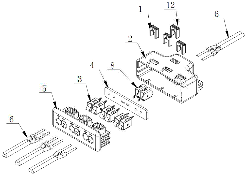
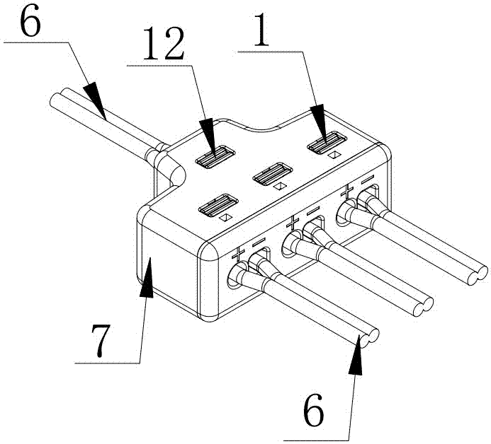
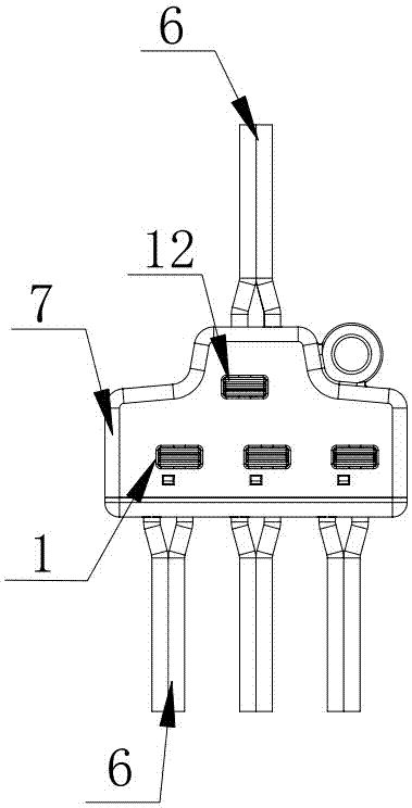
[0059] A terminal shunt connector described in Embodiment 1 of the present invention, such as figure 1 , figure 2 , image 3 , Figure 4 , Figure 5 , Figure 6 , Figure 7 , Figure 8 , Figure 9 , Figure 10 , Figure 11 , Figure 12 , Figure 13 , Figure 14 , Figure 15 , Figure 16 , Figure 17 and Figure 18 As shown, it includes an insulating casing 7 and a front conductive metal piece 3 and a rear conductive metal piece 8 installed in the insulating casing. The insulating casing is provided with a front fixing seat for fixing the front conductive metal piece and a rear fixing seat for fixing the rear conductive metal piece. , the front conductive metal piece and the rear conductive metal piece are connected and energized by welding on the circuit board 4. The circuit board has two forms of parallel connection and series connection. Insertion port 10, the rear part of the insulating shell is provided with the rear inserting port 11 corresponding to the ...

Embodiment 2

[0066] This embodiment 2 changes on the basis of embodiment 1, specifically:

[0067] Such as Figure 25 , Figure 26 , Figure 27 , Figure 28 , Figure 29 , Figure 30 , Figure 31 , Figure 32 , Figure 33 , Figure 34 , Figure 35 and Figure 36 As shown, the front push button and the rear push button are combined with the insulating shell to form an integrated structure, and are self-contained buttons. The insulating housing is composed of an upper housing 28 and a lower housing 29, the front fixing seat and the rear fixing seat are arranged in the lower housing, and the front pressing button and the rear pressing button are arranged on the upper housing; The fixing seat is composed of clamping plates 30 which can fix the wiring metal body, and the wiring metal body is clamped between two clamping plates to form installation and fixation.

[0068] The front push button and the rear push button are self-contained buttons that form an integral structure with the...


PUM


Abstract

The invention discloses a wiring terminal branch connector, comprising an insulation housing, a front conductive metal member, a back conductive metal member, a front fixing seat, a back fixing seat, a circuit board, a front wire plugging port, a back wire-plugging port, a front pressing button and a back pressing button. The front pressing button and the back pressing button form connection and disconnection between the front conductive metal member and the back conductive metal member by cooperating with the front conductive metal member and the back conductive metal member. At least two sets of the front conductive metal members are arranged and one set of the back conductive metal member is arranged; each set of the front conductive metal member and the back conductive metal members consists of two connection metal bodies which are connected side by side; the connection metal body is formed by integrating a square frame, an elastic metal sheet and a plug, wherein the elastic metal sheet is perked from the bottom of the square frame to form a C shape, is inserted inside the square frame and is closely clung to the internal of the top of the square frame, and the plug is connected to and installed on the circuit board; and the top of the connection metal body is provided with a breach for allowing the front pressing button or the back pressing button to pass through, and the elastic metal member can be pressed in the breach.

Description

technical field [0001] The present invention relates to the technical field of a wiring terminal structure, in particular to a plug-in wiring, and both wiring and off-line are realized by pressing a button. Wire access, three groups or six groups or nine groups of positive and negative wires are connected to terminal shunt connectors. Background technique [0002] As a connecting component of electronic components, electrical appliances, etc., terminal blocks can have the effect of wiring and energization, and realize the good connection function of wiring and energization. It is an important wiring component for electrical connection and connection between terminal and terminal. However, the structures of the existing terminal blocks are varied, and the wiring cannot be completed in one step. It is often necessary to disassemble the terminal block and use bolts, rivets, etc. to connect the wires to the terminal block. Wiring process and reduce the efficiency of wiring, inc...

Claims


Application Information

Patent Timeline
Patent Type & Authority Patents(China)
IPC IPC(8): H01R13/629H01R13/02H01R4/48H01R25/00
Inventor 饶小坡尹波青
Owner JIANG MEN TOP ELECTRIC INTELLIGENCE
Why Eureka
Try Eureka