A self-protecting cylinder type permanent magnet transmission device
A permanent magnet transmission, self-protection technology, applied in electromechanical transmissions, electromechanical devices, electric components, etc., can solve the problems of difficult heat dissipation, inability to carry out effective protection, and large radius of high-power devices
- Summary
- Abstract
- Description
- Claims
- Application Information
AI Technical Summary
Problems solved by technology
Method used
Image
Examples
Embodiment
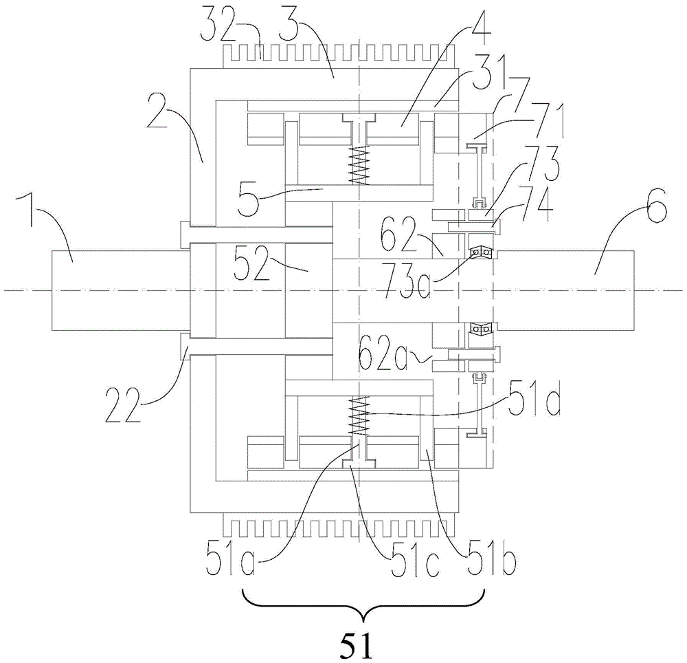
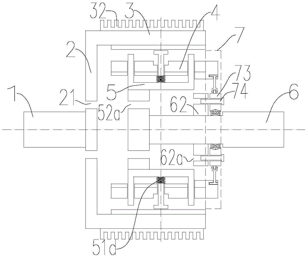
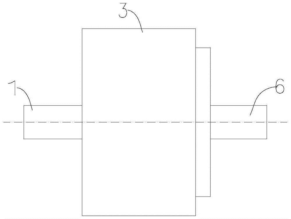
[0038] Figure 1 to Figure 10 , the reference signs are as follows:
[0039] 1. Outer rotor shaft;
[0040] 2. Outer rotor end plate; 21. Outer rotor end plate through hole; 22. Synchronization pin;
[0041] 3. Outer rotor movement cylinder; 31. Conductive metal cylinder; 32. First heat sink;
[0042] 4. Inner rotor rotating cylinder; 41. Permanent magnet; 42. Aluminum disc; 43. Permanent magnet back iron;
[0043] 5. Inner rotor inner rotating cylinder; 51. Fixed rod group; 51a. Main rod; 51b. Secondary rod; 51c. Rod cap; 51d. Centrifugal spring;
[0044] 6. Inner rotor shaft; 61. Axial groove; 62. Shaft flange; 62a. Shaft flange through hole;
[0045] 7. Fan-shaped cylinder push-pull mechanism; 71. Sector-shaped disk; 71a. Sector-shaped disk belt groove; 72. Air gap adjustment rod; 72a. Pull rod pin; 73. Rotary disk; 73a. 73c. Rotating disk through hole; 74. Lock pin.
[0046] Such as figure 1 As shown, a variable air gap self-protection barrel type permanent magnet spe...
PUM
 Abstract
Description
Claims
Application Information
 - R&D
- Intellectual Property
- Life Sciences
- Materials
- Tech Scout
- Unparalleled Data Quality
- Higher Quality Content
- 60% Fewer Hallucinations
Browse by: Latest US Patents, China's latest patents, Technical Efficacy Thesaurus, Application Domain, Technology Topic, Popular Technical Reports.
© 2025 PatSnap. All rights reserved.Legal|Privacy policy|Modern Slavery Act Transparency Statement|Sitemap|About US| Contact US: help@patsnap.com


