
Variable air gap self-protection cylinder permanent protection speed regulator

A permanent magnet governor and self-protection technology, which is applied to permanent magnet clutches/brakes, electrical components, cooling/ventilation devices, etc., can solve problems such as ineffective protection, large radius of high-power devices, and difficulty in heat dissipation

Active Publication Date: 2015-10-14
江苏南自通华智慧能源股份有限公司
View PDF5 Cites 2 Cited by
  • Summary
  • Abstract
  • Description
  • Claims
  • Application Information

AI Technical Summary

Problems solved by technology

The disc structure usually adopts the form of changing the thickness of the air gap, which is convenient for protection, but the high-power device needs a large radius and has difficulty in heat dissipation; the barrel structure usually adopts the method of changing the effective target area, which can be extended infinitely to increase the power. And the heat dissipation is convenient, but because the air gap does not change, it cannot effectively protect

Method used


Image

  • Variable air gap self-protection cylinder permanent protection speed regulator
  • Variable air gap self-protection cylinder permanent protection speed regulator
  • Variable air gap self-protection cylinder permanent protection speed regulator

Examples


Embodiment 1

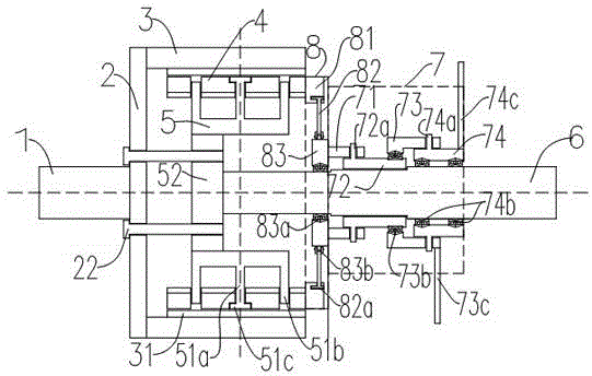
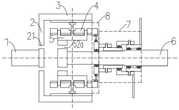
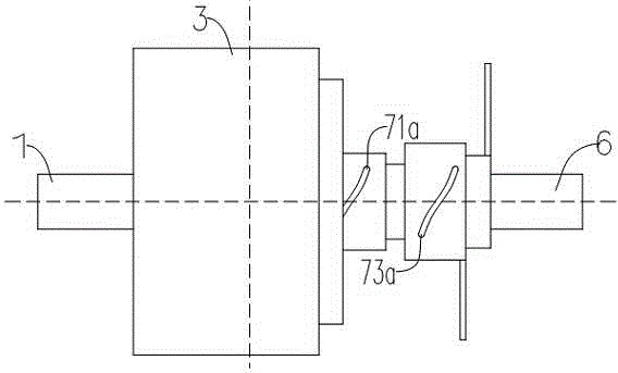
[0045] Such as figure 1 , 2 As shown in and 3, a variable air gap self-protection cylinder type permanent magnet speed governor includes an inner rotor and an outer rotor coaxially arranged.

[0046] The outer rotor includes an outer rotor shaft 1, an outer rotor end plate 2 and an outer rotor moving cylinder 3. The outer rotor moving cylinder 3 is coaxially arranged with the outer rotor shaft 1, and is connected to the outer rotor shaft 1 through the outer rotor end plate 2. connected, the outer rotor moving cylinder 3 can rotate synchronously with the rotation of the outer rotor shaft 1 .

[0047] The inner rotor includes an inner rotor shaft 6, an inner rotor rotating cylinder 4, an inner rotor inner rotating cylinder 5, a fan-shaped cylinder push-pull mechanism 8, a rotating disk rotating mechanism 7 and a radial fixed guide assembly. The inner rotor rotating cylinder 4 is arranged coaxially with the inner rotor shaft 6 , and the inner rotor rotating cylinder 4 can rotat...

Embodiment 2

[0085] Embodiment 2 is basically the same as the first rotary structure of embodiment 1, the difference lies in the addition of a water-cooling structure 91, specifically as follows:

[0086] The cooling water supply and drainage system 91 includes a cooling water supply and drainage pipeline 93 , a cooling water collector 92 and an external heat exchange mechanism 91 .

[0087] The cooling water collector 92 is coaxially sleeved in the middle of the outer rotor shaft 1 and connected with the external heat exchange mechanism 91 .

[0088] The cooling water supply and discharge pipeline 93 is evenly arranged in the sealed cavity, and the inlet end and the outlet end of the cooling water supply and discharge pipeline 93 are respectively connected with the cooling water collector 92 .

[0089] The cooling water collector 92 includes a cooling water supply chamber 92a and a cooling water recovery chamber 92b. The inlet end of the cooling water supply and drainage pipeline 93 is co...


PUM


Abstract

The present invention discloses a variable air gap self-protection cylinder permanent protection speed regulator which comprises an inner rotor and an outer rotor. The inner rotor comprises an inner rotor shaft, an inner rotor rotation cylinder, an inner rotor inner rotation cylinder, a fan-shaped cylinder pushing and pulling mechanism, a rotation disk rotation mechanism and a radial fixed guide component. The inner rotor rotation cylinder is formed by enclosing a plurality of concentrically arranged fan-shaped cylinders. The outer rotor comprises an outer rotor shaft, an outer rotor end disk, an outer rotor movement cylinder and a conductive metal cylinder. Through the common effect of the fan-shaped cylinder pushing and pulling mechanism, the rotation disk rotation mechanism and the radial fixed guide component, each of the fan-shaped cylinder radially and synchronously moves along the inner rotor rotation cylinder with the center of the inner rotor rotation cylinder as the center, thus a variable air gap is increased or reduced, and the purpose of speed adjustment is achieved. According to the permanent protection speed regulator, while the advantages of the power and heat radiation aspects of a cylinder structure are maintained, the performance of speed adjustment and self protection is realized by using an air gap thickness adjustment mode, and the variable air gap self-protection cylinder permanent protection speed regulator is suitable for a large power device.

Description

technical field [0001] The invention relates to a speed governor, in particular to a variable air gap self-protection cylinder type permanent magnet speed governor. Background technique [0002] The existing permanent magnet eddy current speed regulating device is mainly composed of a permanent magnet rotor and a conductor (such as copper) rotor. Generally, the motor shaft and the working machine shaft are respectively connected to one of the rotors, and there is an air gap (called air gap) between the conductor rotor and the permanent magnet rotor, and there is no mechanical connection for torque transmission. In this way, a soft (magnetic) connection is formed between the motor and the working machine, and the shaft torque and speed of the working machine can be changed by adjusting the air gap, so it can adapt to various harsh environments, and because there is no direct mechanical connection, it can reduce Mechanical loss. [0003] In the existing structure, there are ...

Claims


Application Information

Patent Timeline
IPC IPC(8): H02K49/10H02K9/19
Inventor 徐魁金平常新平陈晓菊张锋殷杰许多
Owner 江苏南自通华智慧能源股份有限公司
Learn More