Signal source separation

A signal separation and signal technology, applied in the field of separation of signal sources, can solve problems such as insufficient separation of microphones, and achieve the effects of improving clarity, high performance, and reducing error rates

Inactive Publication Date: 2015-10-21
ANALOG DEVICES INC
View PDF6 Cites 16 Cited by
  • Summary
  • Abstract
  • Description
  • Claims
  • Application Information

AI Technical Summary

Problems solved by technology

However, beamforming methods may be limited, for ex

Method used


Image

  • Signal source separation
  • Signal source separation
  • Signal source separation

Examples


Embodiment Construction

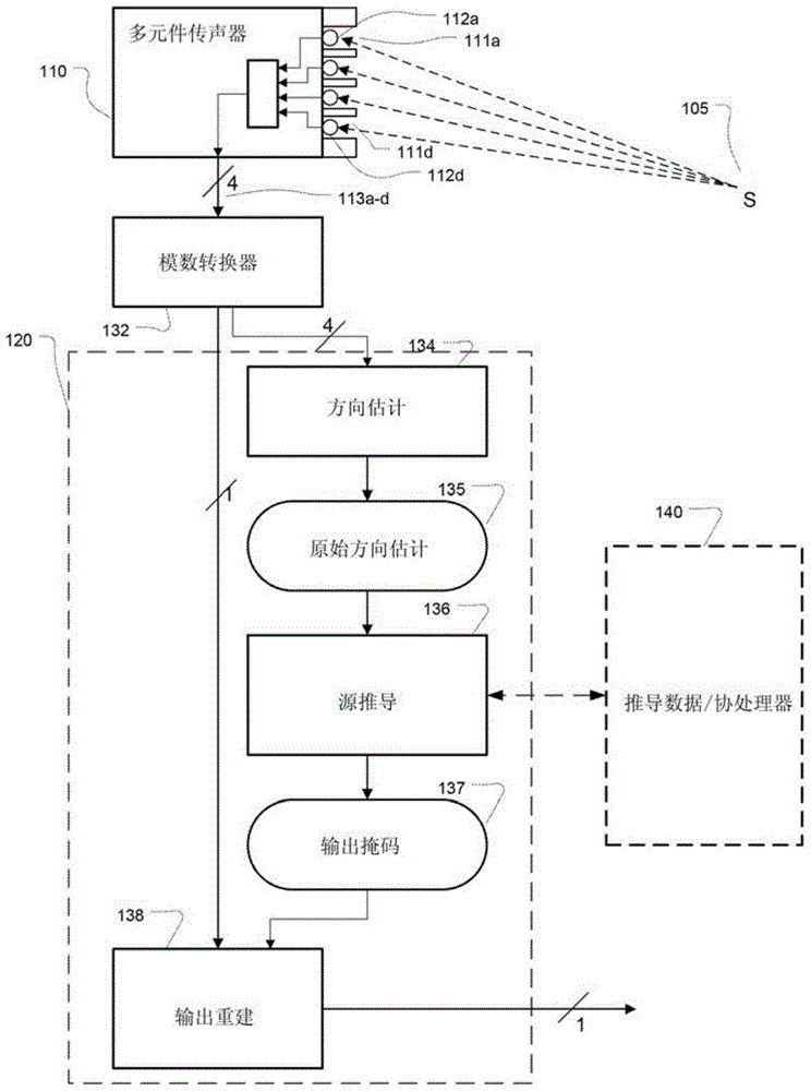
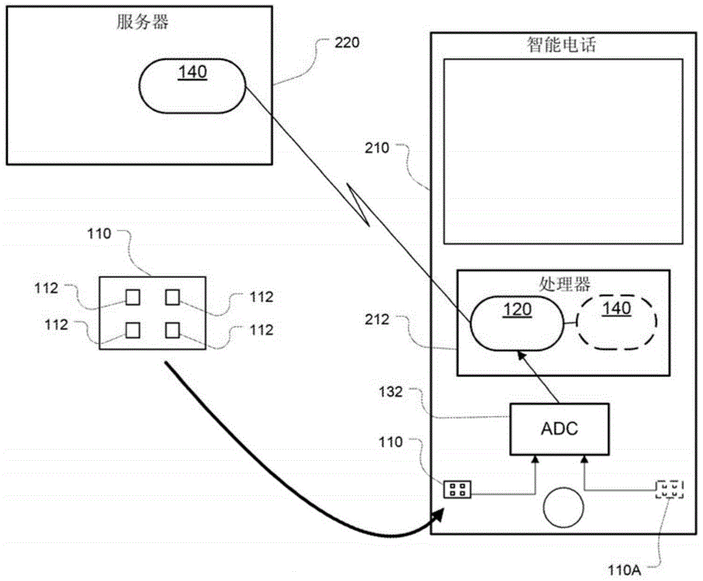
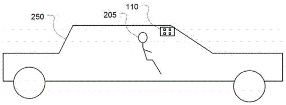
[0067] In general, various embodiments described herein are directed to the problem of receiving an audio signal (e.g., acquiring an acoustic signal) and processing the signal to separate (e.g., extract, identify) the signal from a particular source, e.g., for use in communication Systems for communicating extracted audio signals (eg, telephone networks) or using computer-based analytical processing for purposes (eg, automatic speech recognition and natural language understanding). refer to Figure 2A -B, Application of these methods can be used in a personal computing device, such as a smart phone 210 that uses a microphone 110 to capture and process a user's voice signal, having a plurality of elements 112 (optionally including one or more other multi-elements 110A) , or in the vehicle 250 processing the driver's voice signal. As further described below, the microphone passes the signal to the analog-to-digital converter 132, and the signal is then processed using the proce...


PUM


Abstract

In one aspect, a microphone with closely spaced elements is used to acquire multiple signals from which a signal from a desired source is separated. The signal separation approach uses a combination of direction-of-arrival information or other information determined from variation such as phase, delay, and amplitude among the acquired signals, as well as structural information for the signal from the source of interest and/or for the interfering signals. Through this combination of information, the elements may be spaced more closely than may be effective for conventional beamforming approaches. In some examples, all the microphone elements are integrated into a single a micro-electrical-mechanical system (MEMS).

Description

[0001] Cross Reference Related Applications [0002] This application claims the benefit of the following applications: [0003] · U.S. Provisional Application No. 61 / 764290, titled "SIGNAL SOURCE SEPARATION," filed February 13, 2013; [0004] · U.S. Provisional Application No. 61 / 788521, entitled "SIGNAL SOURCE SEPARATION," filed March 15, 2013; [0005] · U.S. Provisional Application No. 61 / 881678, entitled "TIME-FREQUENCY DIRECTIONAL FACTORIZATION FOR SOURCE SEPARATION," filed September 24, 2013; [0006] · U.S. Provisional Application No. 61 / 881709, filed September 24, 2013, entitled "SOURCE SEPARATION USING DIRECTION OF ARRIVAL HISTOGRAMS"; and [0007] · US Provisional Application No. 61 / 919851, filed December 23, 2013, entitled "SMOOTHING TIME-FREQUENCY SOURCE SEPARATION MASKS." Each is incorporated herein by reference. [0008] This application is also related to, but does not claim benefit from, the filing date of International Application PCT / US2013 / 060044, filed S...

Claims


Application Information

Patent Timeline
IPC IPC(8): G10L21/0272
CPCG10L21/0272H04R1/406H04R2201/003H04R2430/21
Inventor D·温格特N·斯特因
Owner ANALOG DEVICES INC
Why Eureka
Try Eureka