Elevator brake release device

A technology of elevator brakes and brakes, which is applied in hoisting devices, transportation and packaging, elevators, etc., can solve problems such as inability to guarantee personnel safety, failure of electric brake release, failure of main engine to release brakes, etc., and achieves high synchronization and installation space requirements Small, the effect of avoiding electrical failure failure

Active Publication Date: 2017-10-27
HITACHI ELEVATOR CHINA
View PDF7 Cites 0 Cited by
  • Summary
  • Abstract
  • Description
  • Claims
  • Application Information

AI Technical Summary

Problems solved by technology

[0002] At present, machine-room-less elevators are developing very rapidly. With the further popularization and application of machine-room-less elevators, the demand for machine-room-less elevators in the market is also increasing. Neglected problem, the main engine of the existing machine room-less elevator is installed in the shaft, people cannot directly operate the main machine to release the brake like the machine room elevator, and need to operate the brake release device outside the shaft
At present, machine-room-less elevators generally operate the electrical switch outside the shaft to release the brakes electrically, but elevators often fail to release the electric brakes due to faults in the brake coil and terminal block, which is prone to failure and cannot guarantee the safety of personnel.

Method used


Image

  • Elevator brake release device
  • Elevator brake release device
  • Elevator brake release device

Examples


Embodiment Construction

[0027] Embodiments of the present invention are described in detail below in conjunction with accompanying drawings:

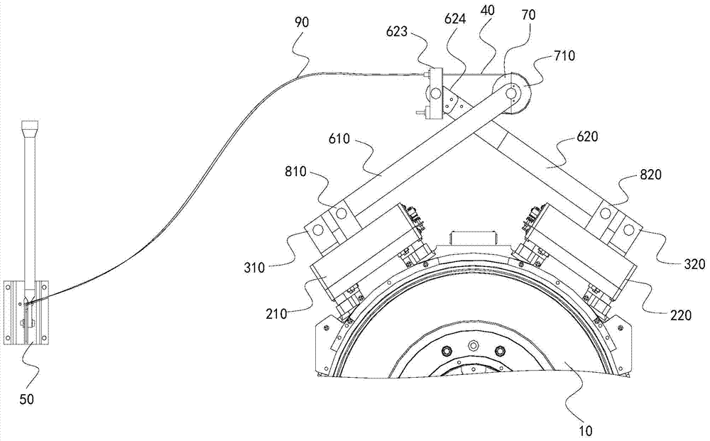
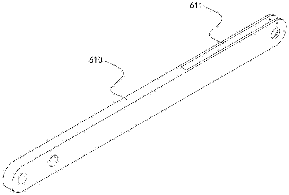
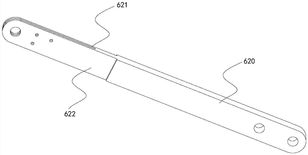
[0028] Such as Figure 1 to Figure 3 As shown, a brake release device for an elevator includes a first brake 210 and a second brake 220, a first support 310 and a second support 320 symmetrically arranged on the elevator host 10, and it also includes a control rope 40, a The out-of-hole brake release operating mechanism 50 for tightening or loosening the control rope 40, the first pull rod 610 and the second pull rod 620 arranged crosswise, one end of the first pull rod 610 is rotatably connected to the first support 310, and the other end is connected to a pulley 70. The first pull rod 610 is provided with an active groove 611, one end of the second pull rod 620 is movably connected with the second support 320, the other end passes through the active groove 611 and is connected with one end of the control rope 40, and the other end of the control rope 40 is b...


PUM


Abstract

The invention relates to an elevator brake releasing device. The elevator brake releasing device comprises a first brake, a second brake, a first support and a second support, wherein the first brake and the second brake are symmetrically arranged on an elevator host. The elevator brake releasing device further comprises a control rope, an outside well releasing operating mechanism used for tensioning or releasing the control rope, a first pull rod and a second pull rod, wherein the first pull rod and the second pull rod are arranged in a crossed mode. One end of the first pull rod is rotationally connected with the first support, and a pulley is connected to the other end of the first pull rod. The first pull rod is provided with a movable groove. One end of the second pull rod is movably connected with the second support. The other end of the second pull rod penetrates through the movable groove and is connected with one end of the control rope. The other end of the control rope winds around the pulley to be connected with the outside well releasing operating mechanism. The first brake and the second brake are connected with the first pull rod and the second pull rod respectively. According to the elevator brake releasing device, releasing is carried out in a mechanical mode, the problem of failure of the releasing device due to electric failure can be solved, and safety and reliability are achieved. The first pull rod and the second pull rod are arranged in the crossed mode, the synchronism of releasing of the first brake and the second brake is high, and brake force is stable.

Description

technical field [0001] The invention relates to the technical field of elevator brake release, in particular to an elevator brake brake release device. Background technique [0002] At present, machine-room-less elevators are developing very rapidly. With the further popularization and application of machine-room-less elevators, the demand for machine-room-less elevators in the market is also increasing. The neglected problem is that the main engine of the existing machine-room-less elevator is installed in the well, and people cannot directly operate the main engine to release the brake like the machine-room elevator, and need to operate the brake release device outside the well. At present, machine-room-less elevators generally operate the electrical switch outside the well to release the brakes electrically. However, elevators often fail to release the brakes electrically due to faults in the brake coil and terminal block, which is prone to failure and cannot guarantee th...

Claims


Application Information

Patent Timeline
Patent Type & Authority Patents(China)
IPC IPC(8): B66D5/24B66B5/02
CPCB66B5/00B66D5/24
Inventor 黄涛黄宗耀唐电波
Owner HITACHI ELEVATOR CHINA
Why Eureka
Try Eureka