Rotary compressor and its crankshaft

A technology for rotating compressors and crankshafts, applied in the field of compressors, can solve the problems of increased wear of crankshafts and bearings, stricter requirements on magnetic permeability, and increased operating resistance of compressors, so as to reduce gas resistance, reduce weight, and reduce The effect of eccentric mass

Active Publication Date: 2019-04-05
GUANGDONG MEIZHI COMPRESSOR +1
View PDF7 Cites 0 Cited by
  • Summary
  • Abstract
  • Description
  • Claims
  • Application Information

AI Technical Summary

Problems solved by technology

Using this method can effectively reduce the noise and vibration of the compressor, but since the balance weight is installed on the motor rotor, in order to avoid the decline of the motor efficiency, the requirements for the magnetic permeability of the balance weight material are relatively strict, resulting in high cost of the balance weight material
In addition, after the balance weight is added to the motor rotor, the balance weight will be subjected to a large gas force during the operation of the compressor, which will increase the running resistance of the compressor, resulting in a decrease in the energy efficiency of the compressor, and even the high-speed rotation of the compressor. The middle balance weight produces a large inertial force, which will also increase the wear between the crankshaft and the bearing when the inertial force acts on the crankshaft

Method used


Image

  • Rotary compressor and its crankshaft
  • Rotary compressor and its crankshaft
  • Rotary compressor and its crankshaft

Examples


Embodiment 1

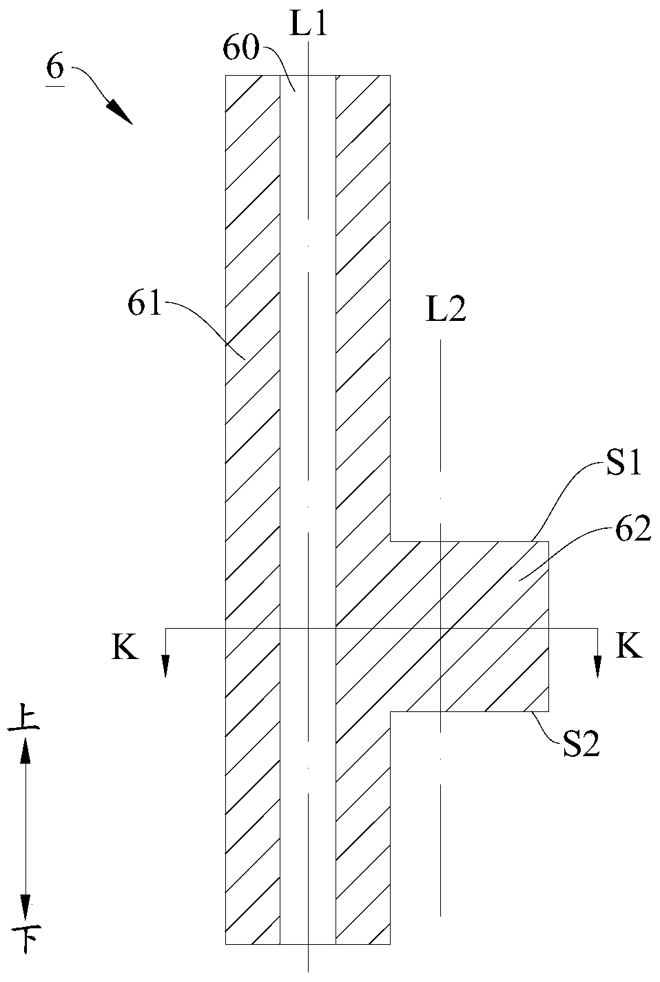
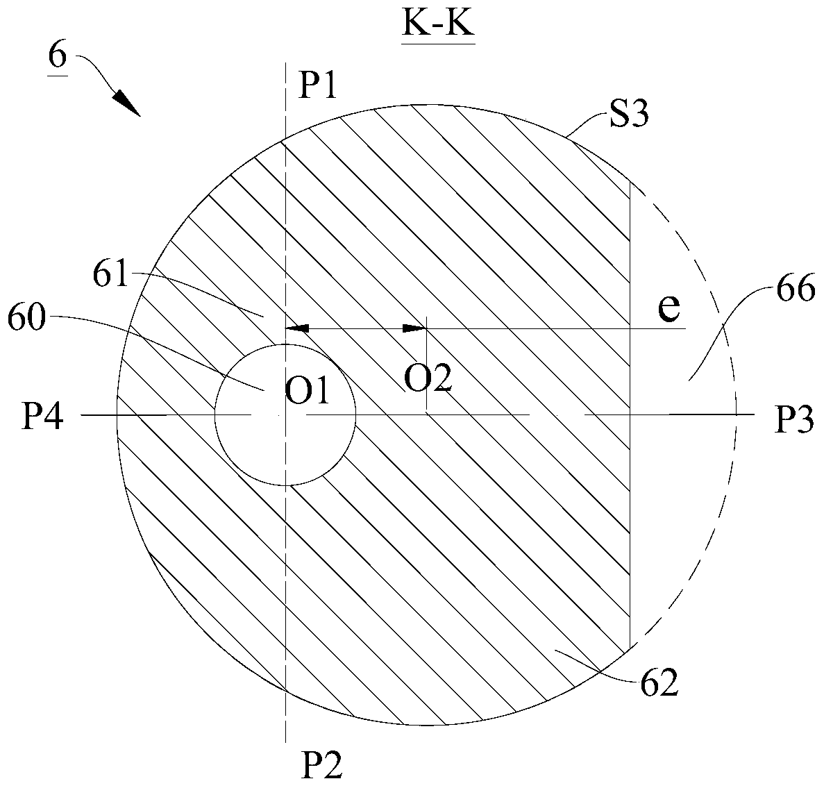
[0056] In this example, if figure 2 with image 3 As shown, the trimming portion 66 passes through the upper end surface S1 and the lower end surface S2 of the eccentric portion 62 .

[0057] Advantageously, the cut plane formed by the trimming portion 66 on the eccentric portion 62 is parallel to the central axis L1 of the main shaft portion 61 . That is to say, the trimming portion 66 is formed tangentially on the eccentric portion 62 by a plane parallel to the central axis L1 of the main shaft portion 61 , and the cross section of the trimming portion 66 is arcuate. Therefore, the trimming portion 66 is more convenient to process, the production cost of the crankshaft 6 is lower, and the eccentric mass of the eccentric portion 62 can be greatly reduced. Wherein, the cross-section of the trimming portion 66 refers to a cross-sectional profile formed on the trimming portion 66 on a plane perpendicular to the central axis L1 of the main shaft portion 61 .

[0058] Of cours...

Embodiment 2

[0061] In this example, if Figure 4 with Figure 5 As shown, the structure of the crankshaft 6 is substantially the same as the structure of the crankshaft 6 in the first implementation, and this will not be repeated.

[0062] The difference is that in the second embodiment, the eccentric part 62 is provided with a weight-reducing balance hole 63 , so that the eccentric mass of the eccentric part 62 can be greatly reduced.

[0063] Specifically, the weight-reducing balance hole 63 is a through hole penetrating the eccentric portion 62 up and down, thus, the processing of the weight-reducing balance hole 63 is more convenient, and the production cost of the crankshaft 6 is lower. In the first embodiment, the cross-sectional shape and cross-sectional area of ​​the weight-reducing balance hole 63 remain unchanged along the axial direction of the crankshaft 6 , which ensures that the manufacturing process of the crankshaft 6 is relatively simple.

[0064] More specifically, as ...

Embodiment 3

[0068] In this example, if Image 6 with Figure 7 As shown, the structure of the crankshaft 6 is substantially the same as the structure of the crankshaft 6 in the first implementation, and this will not be repeated.

[0069] The difference is that, in the third embodiment, the weight-reducing balance hole 63 further includes: side weight-reducing holes 632 , which are located on both sides of the central weight-reducing hole 631 and are symmetrical about the second longitudinal plane P3P4. Therefore, the rotary eccentric inertial force of the rotary compressor 100 using the crankshaft 6 is further reduced, the vibration and noise of the compressor are reduced, and the weight of the balance weight 13 in the compressor is conveniently reduced.

[0070] Advantageously, one end of each side weight-reducing hole 632 extends to the first longitudinal plane P1P2, so that the cross-sectional area of ​​the weight-reducing balance hole 63 is larger, and the eccentric mass of the ecce...


PUM


Abstract

The invention discloses a rotary compressor and its crankshaft. The crankshaft comprises a main shaft part and an eccentric part formed on the main shaft part. A trimming part is formed on the eccentric part. The trimming part passes through the upper end face of the eccentric part or passes through the lower end face of the eccentric part. According to the crankshaft of the embodiment and under the precondition of keeping eccentric magnitude of the crankshaft unchanged, eccentric mass of the crankshaft is mitigated, and distance from the center of gravity of the crankshaft to the rotating center axis is shortened. Meanwhile, rotating eccentric inertia force of the rotary compressor with the application of the crankshaft is minimized, vibration and noise of the compressor are decreased, and long-term running reliability of the compressor is raised. In addition, with the decreasing of the rotating eccentric inertia force, it can be convenient to reduce weight of a balancing piece inside the compressor and even avoid the use of the balancing piece so as to reduce manufacturing cost of the compressor. And air resistance applied on the balancing piece can be reduced during operation, and energy efficiency of the compressor can be enhanced.

Description

technical field [0001] The invention relates to the field of compressors, in particular to a rotary compressor and a crankshaft thereof. Background technique [0002] For rotary compressors, the main working part is the rolling piston nested on the eccentric crankshaft. When the compressor motor is powered on, the eccentric crankshaft connected to the motor rotor will drive the rolling piston to do eccentric movement in the compression chamber of the pump body. Thereby realizing the compression of the refrigerant gas. This type of mechanism is widely used in various refrigeration equipment technical fields due to its simple structure and high compression efficiency. [0003] Due to the eccentric rotation structure, the center of gravity of the moving parts is not on the rotating shaft, so the compressor will generate a rotational inertial force when it is running, and its direction points to the eccentric direction. The existence of eccentric inertial force will increase t...

Claims


Application Information

Patent Timeline
Patent Type & Authority Patents(China)
IPC IPC(8): F16C3/08F16C3/20F04C29/00
Inventor 吴灏刘科种
Owner GUANGDONG MEIZHI COMPRESSOR
Why Eureka
Try Eureka