Rotary compressor and crankshaft thereof

A technology for rotating compressors and crankshafts, applied in the field of compressors, can solve the problems of increasing the running resistance of compressors, increasing wear of crankshafts and bearings, and stricter requirements on magnetic permeability, and reducing gas resistance and rotating eccentric inertial force. The effect of reducing, reducing weight

Inactive Publication Date: 2015-10-07
GUANGDONG MEIZHI COMPRESSOR +1
View PDF6 Cites 0 Cited by
  • Summary
  • Abstract
  • Description
  • Claims
  • Application Information

AI Technical Summary

Problems solved by technology

Using this method can effectively reduce the noise and vibration of the compressor, but since the balance weight is installed on the motor rotor, in order to avoid the decline of the motor efficiency, the requirements for the magnetic permeability of the balance weight material are relatively strict, resulting in high cost of the balance weight material
In addition, after the balance weight is added to the motor rotor, the balance weight will be subjected to a large gas force during the operation of the compressor, which will increase the running resistance of the compressor, resulting in a decrease in the energy efficiency of the compressor, and even the high-speed rotation of the compressor. The middle balance weight produces a large inertial force, which will also increase the wear between the crankshaft and the bearing when the inertial force acts on the crankshaft

Method used


Image

  • Rotary compressor and crankshaft thereof
  • Rotary compressor and crankshaft thereof
  • Rotary compressor and crankshaft thereof

Examples


Embodiment 1

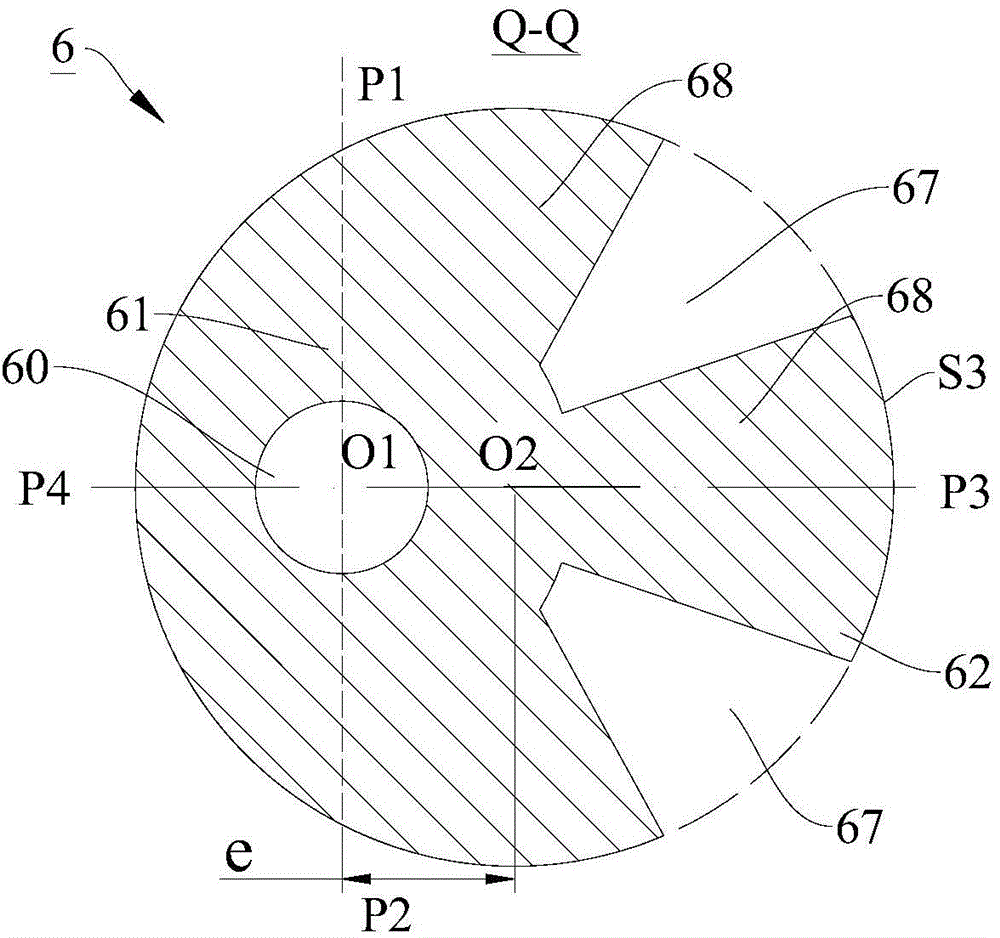
[0058] In this embodiment, as figure 2 with image 3 As shown, a plurality of protrusion structures 68 are provided on the outer peripheral surface of the main shaft portion 61, and two adjacent protrusion structures 68 define a first weight-reducing balance hole 67. That is, the crankshaft 6 cooperates with the piston 12 through a plurality of convex structures 68, or in other words, the outer peripheral surface S3 of the eccentric portion 62 is divided into a plurality of arc surfaces, and the plurality of arc surfaces contact and cooperate with the inner peripheral surface of the piston 12. In this way, the eccentric mass of the eccentric portion 62 is minimized, the rotational eccentric inertia force of the rotary compressor 100 using the crankshaft 6 is reduced, the vibration and noise of the compressor are reduced, and the internal balance of the compressor is also reduced. Weight of block 13.

[0059] In the first embodiment, by providing a plurality of first weight-reduc...

Embodiment 2

[0066] In this embodiment, as Figure 4 with Figure 5 As shown, the structure of the crankshaft 6 is substantially the same as the structure of the crankshaft 6 in the first embodiment, which will not be repeated here.

[0067] The difference is that in the second embodiment, at least one protruding structure 68 is provided with a second weight-reducing balance hole 69, so that the eccentric mass of the eccentric portion 62 can be further reduced, and the rotation of the crankshaft 6 can be reduced. The rotational eccentric inertia force of the compressor 100 reduces the vibration and noise of the compressor, and facilitates the reduction of the weight of the balance weight 13 in the compressor.

[0068] Specifically, the cross-sectional shape of the second weight-reducing balance hole 69 may be a square, a circle, a crescent shape, or a fan shape, and the cross-sectional shape of the second weight-reducing balance hole 69 may also be other shapes. There may be multiple second wei...

Embodiment 3

[0075] In this embodiment, as Figure 8 with Picture 9 As shown, the outer peripheral surface of the main shaft portion 61 is provided with a plurality of connecting plates 621, the free end of each connecting plate 621 is provided with an arc-shaped plate 622, and two adjacent connecting plates 621 define a first weight-reducing balance hole. 67. That is to say, the crankshaft 6 is matched with the piston 12 through a plurality of arc-shaped plates 622, or in other words, the outer peripheral surface S3 of the eccentric portion 62 is divided into a plurality of arc surfaces, and the plurality of arc surfaces are connected to the inner circumference of the piston 12. In this way, the eccentric mass of the eccentric portion 62 can also be minimized, so as to reduce the rotational eccentric inertia force of the rotary compressor 100 using the crankshaft 6, and reduce the vibration and noise of the compressor, which is also convenient This reduces the weight of the balance block ...


PUM


Abstract

The invention discloses a rotary compressor and a crankshaft thereof. The crankshaft comprises a main shaft part and an eccentric part formed on the main shaft part, wherein a first weight-reduction balance hole is formed in the eccentric part, the first weight-reduction balance hole upwards penetrates through the upper end surface of the eccentric part and downwards penetrating through the lower end surface of the eccentric part, and the first weight-reduction balance hole also penetrates through the outer circumferential surface of the eccentric part. According to the crankshaft of the embodiment of the present invention, on the premise of maintaining the eccentricity of the crankshaft, the eccentric weight of the crankshaft can be reduced, the rotary eccentric inertia force of the rotary compressor utilizing the crankshaft can be reduced, the vibration and noise of the compressor can be reduced, and the operation reliability of the compressor for a long time can be improved. Moreover, while the rotary eccentric inertia force is reduced, the weight of a balance block in the compressor can be reduced, even the balance block can be avoided, so that the manufacturing cost of the compressor can be reduced, the air resistance suffered by the balance block when in rotation can be reduced, and the energy efficiency of the compressor can be improved.

Description

Technical field [0001] The present invention relates to the field of compressors, in particular to a rotary compressor and its crankshaft. Background technique [0002] For rotary compressors, the main working component is the rolling piston nested on the eccentric crankshaft. When the compressor motor is energized, the eccentric crankshaft connected to the motor rotor will drive the rolling piston to move eccentrically in the compression chamber of the pump body. So as to realize the compression of refrigerant gas. This type of mechanism is widely used in various refrigeration equipment technical fields due to its simple structure and high compression efficiency. [0003] Because of the eccentric rotating structure, the center of gravity of the moving parts is not on the rotating shaft, so the compressor will generate a rotating inertia force when it is running, and its direction points to the eccentric direction. The presence of eccentric inertial force will increase the vibrat...

Claims


Application Information

Patent Timeline
IPC IPC(8): F04C29/00F16C3/06F16C3/20
Inventor 吴灏刘科种
Owner GUANGDONG MEIZHI COMPRESSOR
Why Eureka
Try Eureka