
Crankshaft, compressor and air conditioner

A technology for compressors and air conditioners, applied in the field of compressors, can solve problems such as the overall performance decline of the compressor, the reduction of compressor efficiency, and the aggravation of crankshaft wear and vibration, so as to ensure overall performance, reduce quality, and avoid wear and vibration. Effect

Active Publication Date: 2022-03-22
GREE ELECTRIC APPLIANCES INC
View PDF3 Cites 0 Cited by
  • Summary
  • Abstract
  • Description
  • Claims
  • Application Information

AI Technical Summary

Problems solved by technology

[0002] Due to the eccentric part of the traditional compressor crankshaft, during the rotation of the crankshaft, the eccentric part and the piston sleeved outside the eccentric part have a large centrifugal force when rotating At the same time, due to the deflection effect of the crankshaft during high-speed operation, the wear and vibration of the crankshaft will be aggravated, resulting in a decrease in compressor efficiency
[0003] In order to solve the above problems, the related technology reduces the eccentric mass of the crankshaft by opening a weight-reducing hole in the eccentric part of the crankshaft, so that the rotational eccentric inertial force is reduced and the compressor's Vibration and noise; however, opening a weight-reducing hole in the eccentric part will affect the oil circuit of the compressor and reduce the overall performance of the compressor

Method used


Image

  • Crankshaft, compressor and air conditioner
  • Crankshaft, compressor and air conditioner

Examples


Embodiment 1

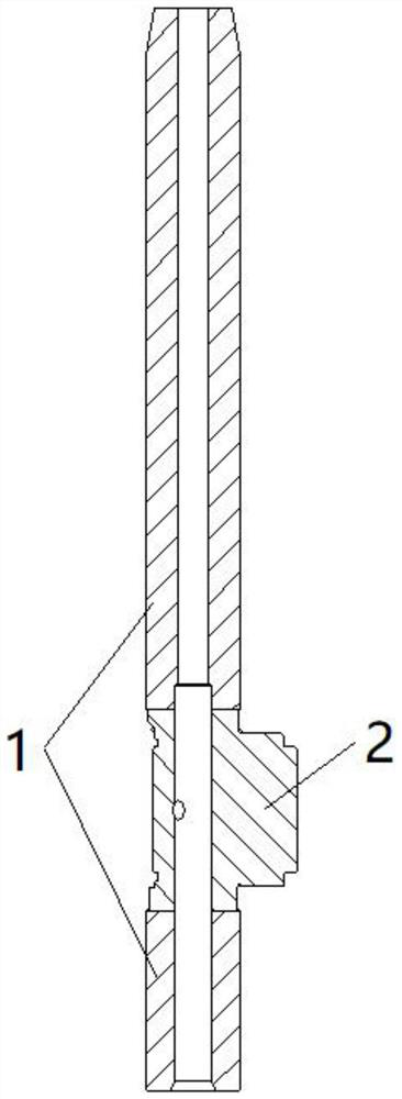
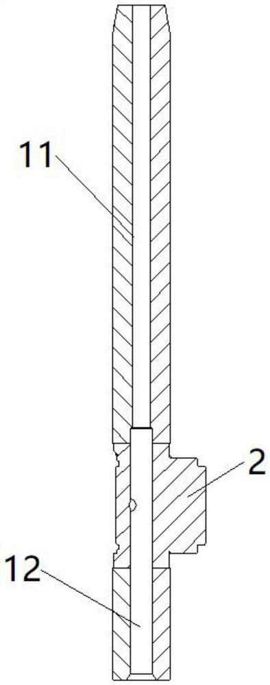
[0029] This embodiment provides a crankshaft, such as figure 1 The crankshaft shown includes a crankshaft body 1 and an eccentric portion arranged on the crankshaft body 1, the eccentric portion 2 is made of a first material, the crankshaft body 1 is made of a second material, and the density of the first material is smaller than that of the second material , used to reduce the mass of the eccentric part 2.

[0030] The eccentric part 2 of the crankshaft is made of the first material, and the crankshaft body 1 is made of the second material, and the density of the first material is smaller than that of the second material, so that the mass of the eccentric part 2 of the crankshaft is reduced, thereby making the rotation of the crankshaft The eccentric inertial forces, ie the centrifugal force, are reduced; in this way wear and vibrations due to deflection effects are avoided.

[0031] Moreover, compared with the traditional method of reducing the eccentric mass of the cranksh...

Embodiment 2

[0056] This embodiment provides a compressor, and the compressor includes the crankshaft of Embodiment 1.

Embodiment 3

[0058] This embodiment provides an air conditioner, and the air conditioner includes the compressor of Embodiment 2.


PUM


Abstract

The crankshaft comprises a crankshaft body and an eccentric part arranged on the crankshaft body, the eccentric part is made of a first material, the crankshaft body is made of a second material, the density of the first material is smaller than that of the second material, and the first material is used for reducing the mass of the eccentric part. The eccentric part of the crankshaft is made of the first material, the crankshaft body is made of the second material, and the density of the first material is smaller than that of the second material, so that the mass of the eccentric part of the crankshaft is reduced, and then the rotating eccentric inertia force of the crankshaft is reduced, namely the centrifugal force is reduced; in this way, abrasion and vibration caused by the perturbation effect are avoided. And moreover, compared with a traditional mode that the eccentric mass of the crankshaft is reduced by forming a lightening hole in the eccentric part of the crankshaft, the structure of the crankshaft does not need to be damaged, so that the oil way structure of the compressor cannot be affected, and the overall performance of the compressor is guaranteed.

Description

technical field [0001] The invention relates to the technical field of compressors, in particular to a crankshaft, a compressor and an air conditioner. Background technique [0002] The traditional compressor crankshaft has an eccentric part. During the rotation of the crankshaft, the eccentric part and the piston sleeved outside the eccentric part have a large centrifugal force when rotating. At the same time, due to the deflection effect of the crankshaft during high-speed operation, the Wear and vibration of the crankshaft, resulting in reduced compressor efficiency. [0003] In order to solve the above problems, related technologies reduce the eccentric mass of the crankshaft by opening a weight-reducing hole in the eccentric part of the crankshaft, so that the rotating eccentric inertial force is reduced, and the vibration and noise of the compressor are reduced; however, setting a weight-reducing hole in the eccentric part will affect the The oil circuit of the compre...

Claims


Application Information

Patent Timeline
Patent Type & Authority Applications(China)
IPC IPC(8): F04C29/00F25B31/00F24F13/00
CPCF04C29/0057F25B31/00F24F13/00
Inventor 余蔚徐嘉杨欧翔邓丽颖赵海红
Owner GREE ELECTRIC APPLIANCES INC
Learn More