Crankshaft for compressor and compressor having same

A compressor and crankshaft technology, applied in the field of compressors, can solve the problems of reducing the reliability of the compressor, unfavorable performance of the compressor, increasing the centrifugal inertial force, etc. Effect

Active Publication Date: 2019-01-04
GUANGDONG MEIZHI COMPRESSOR +1
View PDF6 Cites 0 Cited by
  • Summary
  • Abstract
  • Description
  • Claims
  • Application Information

AI Technical Summary

Problems solved by technology

[0002] In the related art, the crankshaft structure of the rotary compressor is a one-piece casting. Since the crankshaft in the six parts of the pump body of the rotary compressor is generally a solid casting, it is heavy, expensive, and difficult to process.
On the one hand, the mass of the solid eccentric circle of the crankshaft constitutes the main part of the eccentric mass, which will increase the centrifugal inertial force generated by the eccentric mass of the rotary compressor that is not concentric with the axis, thereby reducing the reliability of the compressor; on the other hand, The function of the crankshaft is to transmit the power of the rotor to the pump body. The crankshaft needs to be sufficiently rigid. The casting needs to increase the strength by increasing the wall thickness to prevent deflection and deformation from causing increased bearing wear. The revolution of the crankshaft itself produces useless power consumption. Crankshaft weight dependent, detrimental to compressor performance

Method used


Image

  • Crankshaft for compressor and compressor having same
  • Crankshaft for compressor and compressor having same
  • Crankshaft for compressor and compressor having same

Examples


Embodiment 1

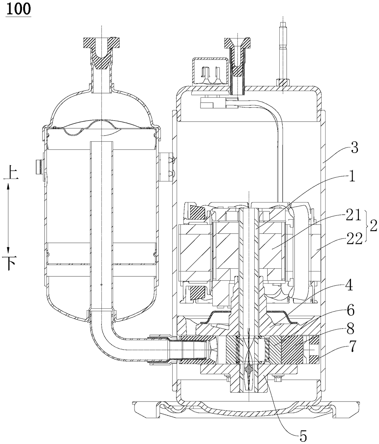
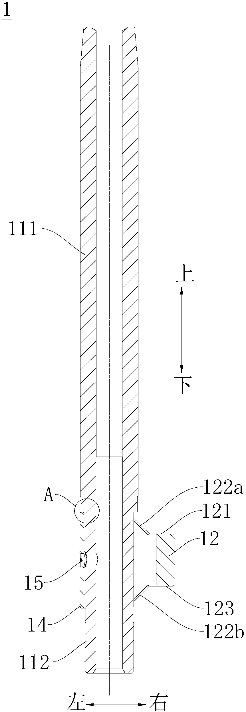
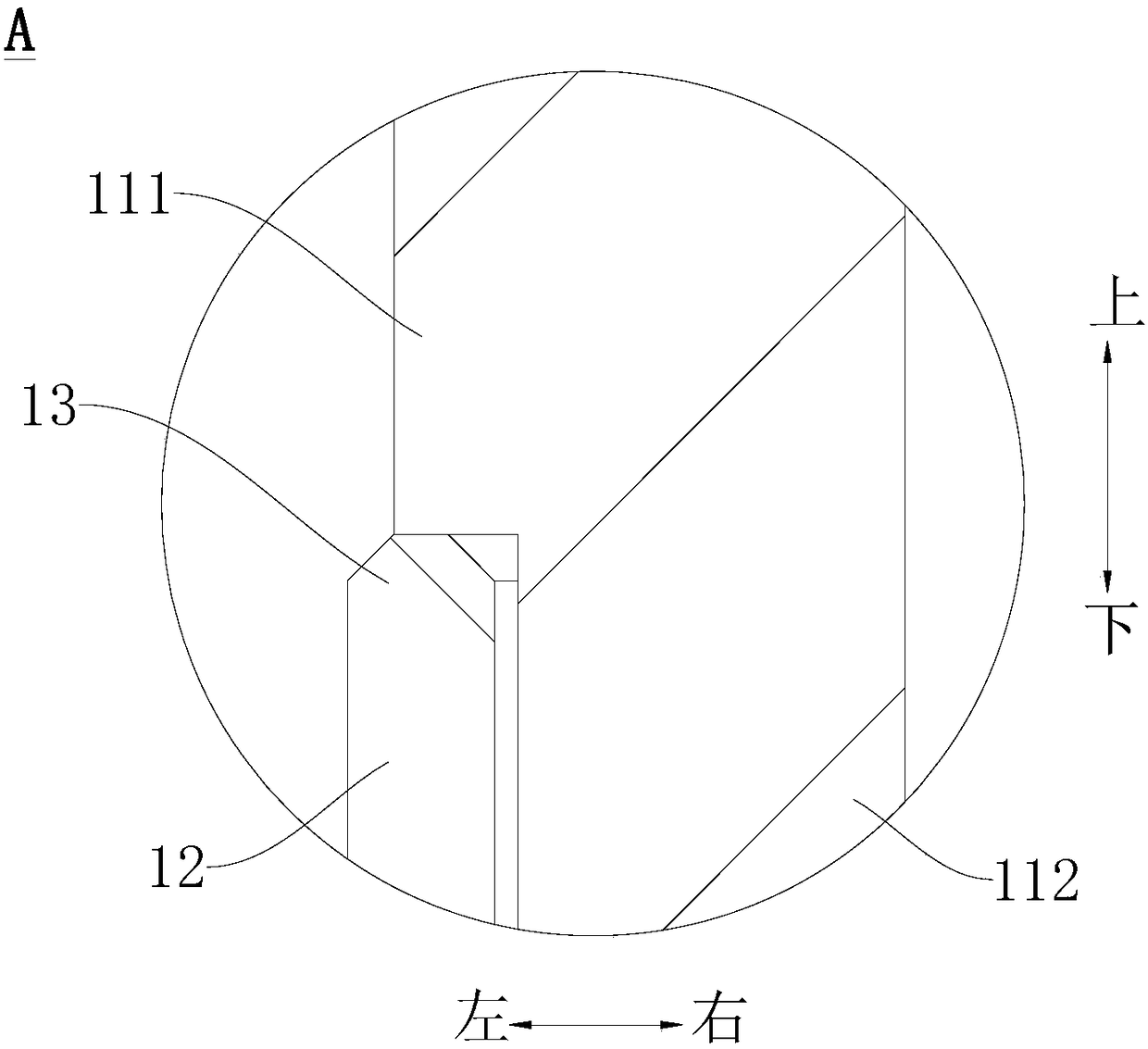
[0047] refer to Figure 2-Figure 5 , in this example, refer to figure 2 and Figure 4 , the crankshaft 1 includes a first pipe body 11 and a second pipe body 12 , and an upper thrust portion 13 protruding upward is integrally formed on the upper end of the second pipe body 12 . Wherein, the first pipe body 11 includes a first section 111 and an end provided at the first section 111 (refer to figure 2 and Figure 4 The second section 112 of the lower end of the first section 111), the outer diameter of the second section 112 is smaller than the outer diameter of the first section 111, and the second pipe body 12 is sheathed on the outer peripheral wall of the second section 112. Thus, the weight of the crankshaft 1 can be further reduced, materials can be saved, and costs can be reduced. What needs to be explained here is that the lower part of the second section 112 of the first pipe body 11 is matched with the auxiliary bearing 5 of the compressor 100, and the outer dia...

Embodiment 2

[0062] refer to Figure 6-Figure 9 , the difference between the crankshaft 1 in this embodiment and the first embodiment above lies in the structure of the second pipe body 12 . Other structures of the crankshaft 1 in this embodiment are substantially the same as those in the first embodiment above, and will not be repeated here. In addition, it should be noted that the same reference numerals are used for the same components in this embodiment as in the first embodiment.

[0063] In this example, refer to Figure 6 and Figure 9 The upper end surface 121 of the second pipe body 12 is a slope inclined downward from the upper surface of the upper thrust portion 13, and the slope extends from the edge of the upper thrust portion 13 downward and obliquely to the right to the bottom of the second pipe body 12. outer edge. Thus, the weight of the second pipe body 12 can be further reduced, that is, the weight of the eccentric portion of the crankshaft 1 can be reduced, thereby ...


PUM


Abstract

The invention discloses a crankshaft for a compressor and the compressor with the crankshaft. The compressor comprises a rotor and a piston. The crankshaft comprises a first pipe and a second pipe. The first pipe is suitable for being arranged in a rotor hole of the rotor so as to be driven by the rotor to rotate. The inner diameter of the second pipe is larger than the outer diameter of the first pipe, and the length of the second pipe is smaller than that of the first pipe. An upper thrust part protruding upwards is integrally formed at the upper end of the second pipe, the first pipe is sleeved with the second pipe, and the center axis of the second pipe deviates from the center axis of the first pipe. The piston is suitable for being arranged on the peripheral wall of the second pipe in a sleeving manner. According to the crankshaft for the compressor, the weight of the crankshaft can be greatly reduced, cost can be reduced, the eccentric mass of the compressor can be reduced, and the reliability of the compressor can be improved; and meanwhile useless power consumption generated by high-speed running of the crankshaft can be reduced, the performance of the compressor can be improved, and the machining technology of the crankshaft can be simplified.

Description

technical field [0001] The invention relates to the technical field of compressors, in particular to a crankshaft for a compressor and a compressor with the same. Background technique [0002] In the related art, the crankshaft structure of the rotary compressor is an integral casting. Since the crankshaft in the six parts of the pump body of the rotary compressor is generally a solid casting, it is heavy, expensive and difficult to process. On the one hand, the mass of the solid eccentric circle of the crankshaft constitutes the main part of the eccentric mass, which will increase the centrifugal inertial force generated by the eccentric mass of the rotary compressor that is not concentric with the axis, thereby reducing the reliability of the compressor; on the other hand, The function of the crankshaft is to transmit the power of the rotor to the pump body. The crankshaft needs to be sufficiently rigid. The casting needs to increase the strength by increasing the wall thi...

Claims


Application Information

Patent Timeline
Patent Type & Authority Patents(China)
IPC IPC(8): F04C29/00F16C3/06
CPCF04C29/00F16C3/06
Inventor 林少坤陈振华栾娜
Owner GUANGDONG MEIZHI COMPRESSOR
Why Eureka
Try Eureka