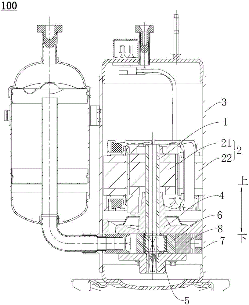
Crankshaft for compressor and compressor with same

A compressor and crankshaft technology, applied in the field of compressors, can solve the problems of reducing compressor reliability, increasing centrifugal inertial force, and unfavorable compressor performance, and achieve the effects of reducing useless power consumption, reducing eccentric mass, and simple structure

Active Publication Date: 2016-08-17
GUANGDONG MEIZHI COMPRESSOR +1
View PDF7 Cites 0 Cited by
  • Summary
  • Abstract
  • Description
  • Claims
  • Application Information

AI Technical Summary

Problems solved by technology

[0002] In the related art, the crankshaft structure of the rotary compressor is a one-piece casting. Since the crankshaft in the six parts of the pump body of the rotary compressor is generally a solid casting, it is heavy, expensive, and difficult to process.
On the one hand, the mass of the solid eccentric circle of the crankshaft constitutes the main part of the eccentric mass, which will increase the centrifugal inertial force generated by the eccentric mass of the rotary compressor that is not concentric with the axis, thereby reducing the reliability of the compressor; on the other hand, The function of the crankshaft is to transmit the power of the rotor to the pump body. The crankshaft needs to be sufficiently rigid. The casting needs to increase the strength by increasing the wall thickness to prevent deflection and deformation from causing increased bearing wear. The revolution of the crankshaft itself produces useless power consumption. Crankshaft weight dependent, detrimental to compressor performance

Method used


Image

  • Crankshaft for compressor and compressor with same
  • Crankshaft for compressor and compressor with same
  • Crankshaft for compressor and compressor with same

Examples


Embodiment Construction

[0029] Embodiments of the invention are described in detail below, examples of which are illustrated in the accompanying drawings. The embodiments described below by referring to the figures are exemplary and are intended to explain the present invention and should not be construed as limiting the present invention.

[0030] In describing the present invention, it is to be understood that the terms "center", "length", "thickness", "upper", "lower", "left", "right", "top", "bottom", "inner ", "outer", "axial", "radial", "circumferential", etc. indicate the orientation or positional relationship based on the orientation or positional relationship shown in the drawings, and are only for the convenience of describing the present invention and simplifying the description. It is not intended to indicate or imply that the referred device or element must have a particular orientation, be constructed in a particular orientation, and operate in a particular orientation, and thus should ...


PUM


Abstract

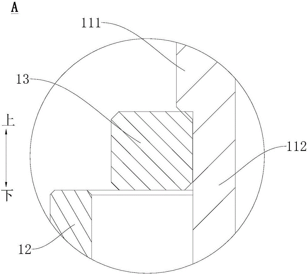
The invention discloses a crankshaft for a compressor and the compressor with the same. The compressor comprises a rotor and a piston; the crankshaft comprises a first pipe body, a second pipe body, an upper thrust part and a lower thrust part; the first pipe body is arranged inside a rotor hole of the rotor for being driven by the rotor to rotate; the second pipe body is arranged outside the first pipe body in a sleeving mode, and the central axis of the second pipe body is deviated from the central axis of the first pipe body; the piston is arranged on the outer peripheral wall of the second pipe body in a sleeving mode; the upper thrust part and the lower thrust part are respectively of a rough C shape, the upper thrust part is arranged on the top of the second pipe body and is arranged on the first pipe body in a sleeving mode, and the lower thrust part is arranged on the bottom of the second pipe body and is arranged on the first pipe body in a sleeving mode. According to the crankshaft, the weight of the crankshaft can be greatly lowered, the cost can be lowered, the eccentric mass of the compressor can be lowered, the reliability of the compressor can be improved, the useless power consumption generated by high-speed operation of the crankshaft can be reduced, and the performance of the compressor can be improved. In addition, the crankshaft is simple in structure and convenient to assemble.

Description

technical field [0001] The invention relates to the technical field of compressors, in particular to a crankshaft for a compressor and a compressor with the same. Background technique [0002] In the related art, the crankshaft structure of the rotary compressor is an integral casting. Since the crankshaft in the six parts of the pump body of the rotary compressor is generally a solid casting, it is heavy, expensive and difficult to process. On the one hand, the mass of the solid eccentric circle of the crankshaft constitutes the main part of the eccentric mass, which will increase the centrifugal inertial force generated by the eccentric mass of the rotary compressor that is not concentric with the axis, thereby reducing the reliability of the compressor; on the other hand, The function of the crankshaft is to transmit the power of the rotor to the pump body. The crankshaft needs to be sufficiently rigid. The casting needs to increase the strength by increasing the wall thi...

Claims


Application Information

Patent Timeline
Patent Type & Authority Applications(China)
IPC IPC(8): F04C29/00F16C3/10
CPCF04C29/00F04C2240/60F16C3/10
Inventor 林少坤陈振华栾娜
Owner GUANGDONG MEIZHI COMPRESSOR
Why Eureka
Try Eureka