Eureka AIR delivers breakthrough ideas for toughest innovation challenges, trusted by R&D personnel around the world.

Ball valve

A technology of ball valves and valve seats, which is applied in the direction of valve devices, cocks including cut-off devices, engine components, etc., can solve the problems of reduced sealing performance, shortened service life, and non-replacement of valves, so as to improve the sealing performance and service life. Effect of improving sealing performance

Inactive Publication Date: 2015-10-28
SHANGHAI LIANKE VALVE COMPLETE EQUIP CO LTD
View PDF8 Cites 0 Cited by
  • Summary
  • Abstract
  • Description
  • Claims
  • Application Information

AI Technical Summary

Problems solved by technology

[0003] see figure 1 As shown, the existing ball valve generally includes a valve body 10, a ball 20, a valve seat, a valve stem 40 and a handle. A fluid through hole 50 is arranged between the inlet and the outlet of the valve body, and the ball is arranged at the interruption of the valve body fluid through hole. , the ball rotates around the valve stem axis within a quarter of the circle between the closed state and the open state; there is a gap between the seal and the ball, and the seal between the ball and the valve seat is generally sealed by a seal 60, the seal is It is fixed and cannot be replaced. At this time, the seal between the ball and the seal is a face seal. When the ball shifts, the seal shifts, or the seal wears out, the sealing part of the ball is easy to fall off, shift, and cause the switch to fail. Phenomenon; at this time, because the position of the seal cannot be adjusted and the new seal can not be replaced, it is easy to reduce the sealing performance of the valve and shorten the service life

Method used


Image

  • Ball valve
  • Ball valve

Examples


Embodiment Construction

[0017] In order to make the technical means, creative features, goals and effects achieved by the present invention easy to understand, the present invention will be further described below in conjunction with specific illustrations.

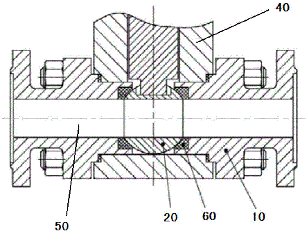
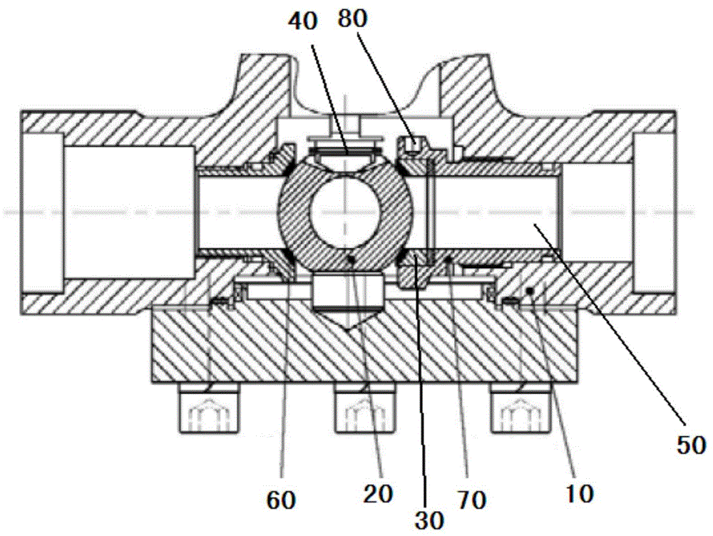
[0018] see figure 2 As shown, the present invention discloses a ball valve, comprising a valve body 10, a ball 20, a valve seat 30, a valve stem 40 and a handle, the valve stem 40 is connected to the ball 20, and the handle is used to drive the valve stem 40 to rotate; the valve body 10 A fluid through hole 50 is provided between the inlet and the outlet, and the ball 20 is arranged at the interruption of the fluid through hole 50 of the valve body, and the ball 20 rotates around the axis of the valve stem within a quarter of a circle between the closed state and the open state; the valve The body 10 is a one-time molding structure, which ensures the mechanical properties of the body material.

[0019] There is generally a gap between the ball...


PUM


Abstract

The invention discloses a ball valve. The ball valve comprises a valve body, a ball body, a valve seat, a valve rod and a handle; a fluid through hole is arranged between an inlet and an outlet of the valve body, the ball body is arranged on the valve body to disconnect the fluid through hole, and the ball body rotates around the axis of the valve rod within a quarter circumference scope between the closing state and the opening state; and a dismountable sealing piece is arranged between the ball body and the valve seat, the sealing piece and the ball body are in linear sealing, the bottom of the sealing piece is arranged on the valve seat, and the sealing piece can move along with the valve seat; and a valve seat sleeve is connected with the valve seat, is arranged in the fluid through hole in a movable manner and is used for adjusting the position of the valve seat. According to the ball valve, the position of the sealing piece is adjustable and replaceable, and the valve seat is adjustable, so that the sealing performance of the ball valve is high, and the service life is greatly prolonged.

Description

technical field [0001] The invention relates to the field of valve devices, in particular to a ball valve. Background technique [0002] At present, the ball valve is mainly used to cut off, distribute and change the flow direction of the medium in the pipeline; the ball valve has a small fluid resistance and a simple structure. It is not only suitable for general working media, but also suitable for media with harsh working conditions. It has been widely used in various fields such as petroleum, chemical industry, power generation, papermaking, atomic energy, aviation, rockets, etc., as well as in people's daily life. [0003] see figure 1 As shown, the existing ball valve generally includes a valve body 10, a ball 20, a valve seat, a valve stem 40 and a handle. A fluid through hole 50 is arranged between the inlet and the outlet of the valve body, and the ball is arranged at the interruption of the valve body fluid through hole. , the ball rotates around the valve stem a...

Claims


Application Information

Patent Timeline
Patent Type & Authority Applications(China)
IPC IPC(8): F16K5/06F16K5/20
CPCF16K5/0689F16K5/201
Inventor 陈锡琦
Owner SHANGHAI LIANKE VALVE COMPLETE EQUIP CO LTD
Why Eureka
Eureka Blog
Learn More