
Fuse mounting structure

An installation structure and fuse technology, applied in emergency protection devices, electrical components, circuits, etc., can solve the problems of low fuse fixing reliability, difficulty in installing fuses, short-circuiting of fuses, etc., so as to avoid short-circuit faults, improve protection and fix The effect is flexible and not easy to short-circuit

Active Publication Date: 2015-10-28
ANHUI JIANGHUAI AUTOMOBILE GRP CORP LTD
View PDF4 Cites 2 Cited by
  • Summary
  • Abstract
  • Description
  • Claims
  • Application Information

AI Technical Summary

Problems solved by technology

[0008] The purpose of the present invention is to provide a technical solution for the installation structure of the fuse, which can not only overcome the problem that the existing fuse is prone to short circuit, but also overcome the difficulty of installing the fuse because the existing vehicle does not have a fuse box specially equipped with the fuse. Problems of high cost and low reliability of fuse fixing

Method used


Image

  • Fuse mounting structure
  • Fuse mounting structure
  • Fuse mounting structure

Examples


Embodiment 1

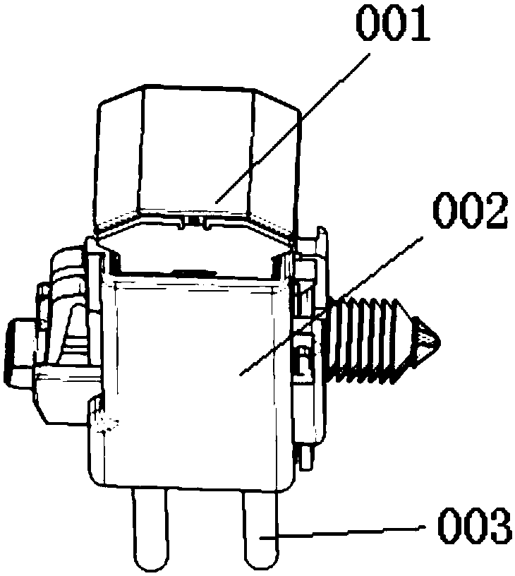
[0059] The present invention provides a fuse installation structure, such as figure 1 As shown, it includes a fuse assembly 001, a fuse base 002 and a wire harness terminal 003; the wire harness terminal 003 is fixed on the fuse base 002; when the fuse assembly 001 is inserted into the fuse base 002, the wire harness terminal 003 into the fuse assembly 001.

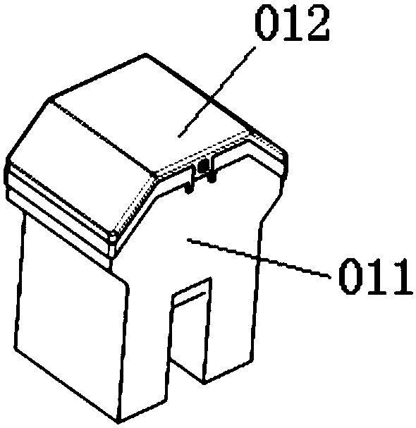
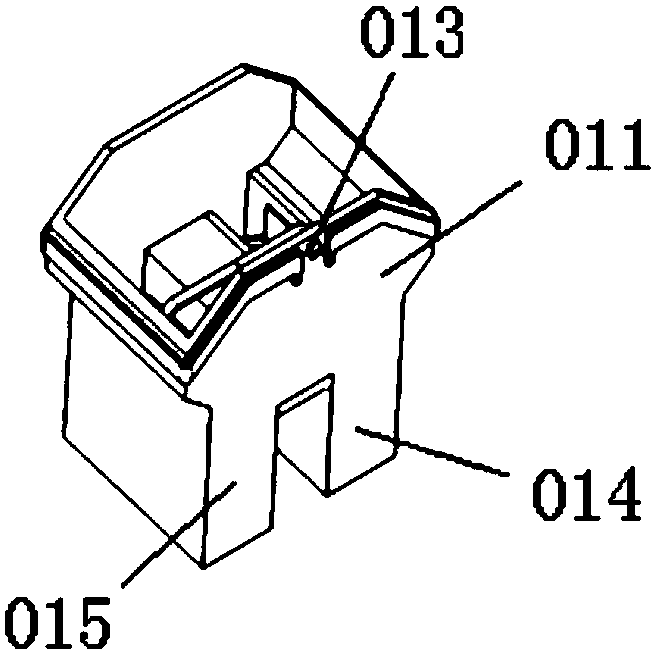
[0060] like Figure 2 to Figure 11 ,and Figure 13 and Figure 16 As shown, the fuse assembly 001 includes a fuse case and a fuse; the fuse is clipped into the fuse case.

[0061] The fuse case includes a case body 011, a case cover 012, a left pin part 014 and a right pin part 015; the upper end of the case body is a two-sided inclined structure, that is, the left pin part and the right pin part are connected at the same time The upper ends of the two sides of the housing are all inclined structures with a high middle and low sides, and the shell cover structure is matched with the structure of the upper end of the s...

Embodiment 2

[0091] The present invention provides a fuse installation structure, such as figure 1 As shown, it includes a fuse assembly 001, a fuse base 002 and a harness terminal 003; the harness terminal is fixed on the fuse base; when the fuse assembly is inserted into the fuse base, the harness terminal is inserted into the fuse Assembly.

[0092] like Figure 2 to Figure 12 ,and Figure 14 to Figure 16 As shown, the fuse assembly includes a fuse case and a fuse; the fuse is clipped into the fuse case.

[0093]The fuse case includes a case body 011, a case cover 012, a left pin part 014 and a right pin part 015; the upper end of the case body is a two-sided inclined structure, that is, the left pin part and the right pin part are connected at the same time The upper ends of the two sides of the housing are all inclined structures with a high middle and low sides, and the shell cover structure is matched with the structure of the upper end of the shell body; the shell cover is clamp...


PUM


Abstract

The present invention relates to a fuse mounting structure comprising a fuse assembly, a fuse base and a wire harness terminal. The wire harness terminal is fixed to the fuse base. When the fuse assembly is inserted into the fuse base, the wiring harness terminal is inserted into the fuse assembly. According to the technical scheme of the invention, through the spacing structure design of a left pin part and a right pin part, a short circuit failure is avoided and the protection is improved, through the four cavity structures with vertical and horizontal baffle plates in a base shell, after a fuse is installed, the internal space is separated, even water and other liquids enter the base, the safety can be ensured, the possibility of short circuit is little, the fuse base and an electrical box are overall separated structures, the cost of a single base is low, and the fuse mounting structure has the advantages of convenience in use, small occupation space and flexible fixation mode.

Description

technical field [0001] The invention belongs to the field of automobile electrical technology, in particular to a fuse installation structure. Background technique [0002] Automobile fuses protect the entire vehicle circuit and are an essential part of the automobile wiring harness, which plays a vital role in the safety of the automobile. The most common fuse installation structure is that the fuse is directly inserted into the electrical box by force and connected to the copper terminal in the fuse box. Automotive high-current fuses are crucial to the electrical safety of the vehicle. [0003] When the automobile fuse is installed, the reliability and stability of the fixing are very important. Only when it is fixed and reliable can the normal operation of the car circuit be guaranteed. Once the fuse is loose and the contact is poor, it will cause a circuit failure in the slightest, and a car fire in the worst case. [0004] The whole of the traditional fuse is a squa...

Claims


Application Information

Patent Timeline
Patent Type & Authority Applications(China)
IPC IPC(8): H01H85/20
CPCH01H85/2015H01H85/2045H01H85/205
Inventor 孙丰超张艳楠汪振兴孟胥里李荫荣王春芝
Owner ANHUI JIANGHUAI AUTOMOBILE GRP CORP LTD
Learn More