Retro guidewire reamer

A technology for guiding wires and cutting components, which is applied in the field of surgical equipment and can solve problems such as the difficulty of realizing bone tunnels

Active Publication Date: 2015-10-28
SMITH & NEPHEW INC
View PDF7 Cites 1 Cited by
  • Summary
  • Abstract
  • Description
  • Claims
  • Application Information

AI Technical Summary

Problems solved by technology

However, because the approach angle is generally not perpendicular to the skin surface, the portal on the patient's skin is

Method used


Image

  • Retro guidewire reamer
  • Retro guidewire reamer
  • Retro guidewire reamer

Examples


Embodiment Construction

[0036] U.S. Provisional Patent Application No. 61 / 776,896, filed March 12, 2013, titled "RETRO GUIDEWIRE REAMER," U.S. Provisional Patent Application No. 61 / 805,578, filed March 27, 2013, titled "RETRO GUIDEWIRE REAMER," and The disclosure of US Provisional Patent Application No. 61 / 858,800, entitled "RETRO GUIDEWIRE LOCK REAMER," filed July 26, 2013, is hereby incorporated by reference in its entirety.

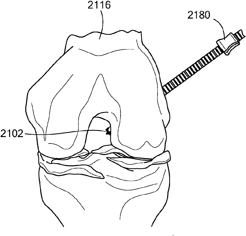
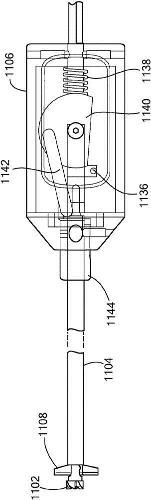
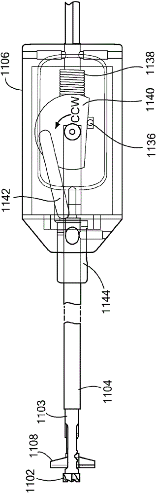
[0037] An exemplary mode of operating the illustrative embodiment of retrograde wire reamer 1100 in accordance with the present application is hereinafter referred to Figure 1-5b to describe. like figure 1 As shown in , the surgeon establishes the desired path for the guide wire 1114 to pass through the femur 1116 . For example, the desired path may be established using a guide (not shown), such as a pinpoint guide or any other suitable guide. The surgeon places guide wire 1114 along the desired path, and removes the guide. The surgeon can then determine the main bone tu...


PUM


Abstract

A retro guidewire reamer includes a cutting member, and a mechanism for moving the cutting member from a closed position to a deployed position in a single manual motion. Once a desired size of a bone tunnel is established, a surgeon uses the reamer to create a primary bone tunnel over a guidewire from the outside in. The surgeon retracts the guidewire, and activates the mechanism to deploy the cutting member within the bone joint to conform to the size of a tendon graft. The surgeon uses the deployed cutting member to create a counter bore through the bone in a retrograde manner. Once the counter bore is drilled, the surgeon activates the mechanism to close the cutting member, allowing the reamer to be withdrawn through the primary tunnel. The retro guidewire reamer can be used to provide more accurate bone tunnel placement during ligament reconstruction surgery.

Description

[0001] Cross References to Related Applications [0002] This application claims U.S. Provisional Patent Application No. 61 / 776,896, filed March 12, 2013, titled "RETRO GUIDEWIRE REAMER," U.S. Provisional Patent Application No. 61, filed March 27, 2013, titled "RETRO GUIDEWIRE REAMER" / 805,578 and priority benefit of U.S. Provisional Patent Application No. 61 / 858,800, filed July 26, 2013, entitled "RETRO GUIDEWIRE LOCK REAMER." technical field [0003] The present application relates generally to surgical devices and methods, and more particularly to surgical devices and methods for creating tunnels through bone tissue during arthroscopic ligament reconstruction surgery. Background technique [0004] For arthroscopic ligament reconstruction surgery, the desired outcome is generally achieved by establishing proper shape and placement of the torn tissue. However, in typical arthroscopic procedures, the cruciate footprint is often hidden from view by soft tissue and residual c...

Claims


Application Information

Patent Timeline
IPC IPC(8): A61B17/16
CPCA61B17/1714A61B17/1615A61B17/1617A61B17/1622A61B17/1624A61B17/1631A61B17/1633A61B17/1675A61B17/1697A61B2017/1602A61B2019/306A61B2090/036
Inventor B.J.布尔奎D.J.卡拉冈M.C.弗拉加莫
Owner SMITH & NEPHEW INC
Why Eureka
Try Eureka