
A device for vacuuming molten metal

A technology of vacuum suction and molten metal, which is applied in the field of casting, can solve the problems of damaged soup intake, difficult detection of molten metal, and inability to swing, so as to avoid leakage and improve the stability of docking

Active Publication Date: 2017-11-17
安徽荣杰精密金属制品有限公司
View PDF9 Cites 0 Cited by
  • Summary
  • Abstract
  • Description
  • Claims
  • Application Information

AI Technical Summary

Problems solved by technology

[0002] At present, in various die-casting industries, the method of ladle soup is commonly used to give soup. This method of taking soup has the disadvantages that the molten metal is easily oxidized, the low-quality soup on the surface is easy to be scooped, and the precision of the soup is low. , The initial setting of the amount of soup is complicated and other disadvantages
On the other hand, because the height of the molten metal in the furnace changes frequently, and the height of the molten metal is difficult to detect, it is impossible to determine the height of the molten metal, and it is impossible to draw the molten metal accurately and quantitatively.
[0003] Now some enterprises still use the vacuum quantitative tank to take soup. The vacuum quantitative tank of this soup taking device is fixed vertically and cannot swing.
It is difficult to dock with the inclined die-casting machine press chamber after taking out the soup, and it is easy to damage the soup taking port or cause the molten metal to leak due to the misalignment of the docking

Method used


Image

  • A device for vacuuming molten metal
  • A device for vacuuming molten metal
  • A device for vacuuming molten metal

Examples


Embodiment Construction

[0038] In order to make the object, technical solution and advantages of the present invention clearer, the present invention will be further described in detail below in conjunction with the accompanying drawings.

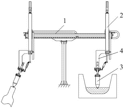
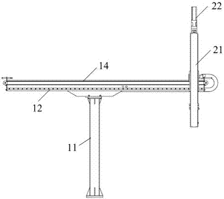
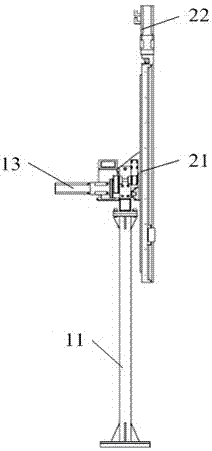
[0039] Such as Figure 1-Figure 8 As shown, the first embodiment of the present invention provides a vacuum pumping equipment for molten metal, including a displacement mechanism and a vacuum quantitative mechanism 3 arranged on the displacement mechanism, and the displacement mechanism is used to drive the vacuum quantitative mechanism 3 to move three-dimensionally , the vacuum quantitative mechanism 3 is used to draw molten metal. Described displacement mechanism comprises transverse movement mechanism 1 and longitudinal movement mechanism 2, and described vacuum quantitative mechanism 3 is arranged on the longitudinal movement mechanism 2, and described longitudinal movement mechanism 2 is arranged on the transverse movement mechanism 1; Described transverse mo...


PUM


Abstract

The invention discloses vacuum molten metal taking equipment. The vacuum molten metal taking equipment comprises a displacement mechanism and a vacuum quantifying mechanism arranged on the displacement mechanism. The displacement mechanism is used for driving the vacuum quantifying mechanism to move in a three-dimensional space. The vacuum quantifying mechanism is used for taking molten liquid. A molten liquid pot is connected with a molten liquid taking position monitoring module, and the molten liquid taking position monitoring module can change the air pressure in the molten liquid pot and determine the molten liquid taking position by monitoring the air pressure in the molten liquid pot. The vacuum quantifying mechanism is connected with the displacement mechanism through a turnover mechanism, and the turnover mechanism can drive the vacuum quantifying mechanism to incline by a certain angle. A weighing sensor is arranged at the joint of the vacuum quantifying mechanism and the turnover mechanism. Due to the fact that the turnover mechanism can drive the vacuum quantifying mechanism to incline by a certain angle, the molten liquid pot can incline to be aligned with a die chamber of a die-casting machine in the molten liquid feeding process, the stability of butt joint of the molten liquid pot and the die chamber of the die-casting machine is improved, and leakage of molten liquid is avoided.

Description

technical field [0001] The invention relates to the technical field of casting, in particular to a device for vacuuming molten metal. Background technique [0002] At present, in various die-casting industries, the method of ladle soup is commonly used to give soup. This method of taking soup has the disadvantages that the molten metal is easily oxidized, the low-quality soup on the surface is easy to be scooped, and the precision of the soup is low. , The initial setting of the amount of soup is complicated and other disadvantages. On the other hand, because the height of the molten metal in the furnace is often changed, and the height of the molten metal is difficult to detect, the height of the molten metal cannot be determined, and the molten metal cannot be drawn quantitatively. [0003] Now some enterprises also get soup by vacuum quantitative tank, and the vacuum quantitative tank of this soup getting device is vertically fixedly arranged, and can not swing. After t...

Claims


Application Information

Patent Timeline
Patent Type & Authority Patents(China)
IPC IPC(8): B22D17/30B22D17/32
Inventor 吕国锋陈伟峰李树高
Owner 安徽荣杰精密金属制品有限公司
Learn More