
Application of DC motor speed control system based on L298N in optical measurement

A DC motor and optical detection technology, applied in the direction of DC motor rotation control, excitation or armature current control, etc., can solve the problems of contact error and low efficiency, achieve accurate measurement results and realize the effect of intelligence

Inactive Publication Date: 2018-12-18
ZHEJIANG GONGSHANG UNIVERSITY
View PDF0 Cites 0 Cited by
  • Summary
  • Abstract
  • Description
  • Claims
  • Application Information

AI Technical Summary

Problems solved by technology

[0006] The main purpose of the present invention is to solve the problems of contact errors and low efficiency caused by manual adjustment of optical measuring instruments based on L298N DC motor speed regulation technology

Method used


Image

  • Application of DC motor speed control system based on L298N in optical measurement
  • Application of DC motor speed control system based on L298N in optical measurement
  • Application of DC motor speed control system based on L298N in optical measurement

Examples


Embodiment Construction

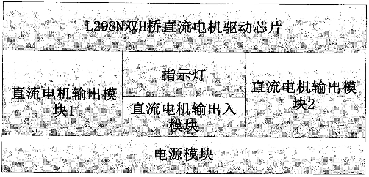
[0020] An embodiment of the present invention is a DC motor speed control system based on L298N, such as figure 1 As shown, the system is mainly composed of two parts, the sending module and the control module.

[0021] The control module is used to control the micro-adjustment of the measurement unit, mainly including the core processor, wireless module, motor drive unit and related peripheral devices.

[0022] The processor can take corresponding control actions after receiving the signal sent by the sending module through the radio frequency module, and realize fine control of the optical adjustment components by controlling the rotation of the motor structure.

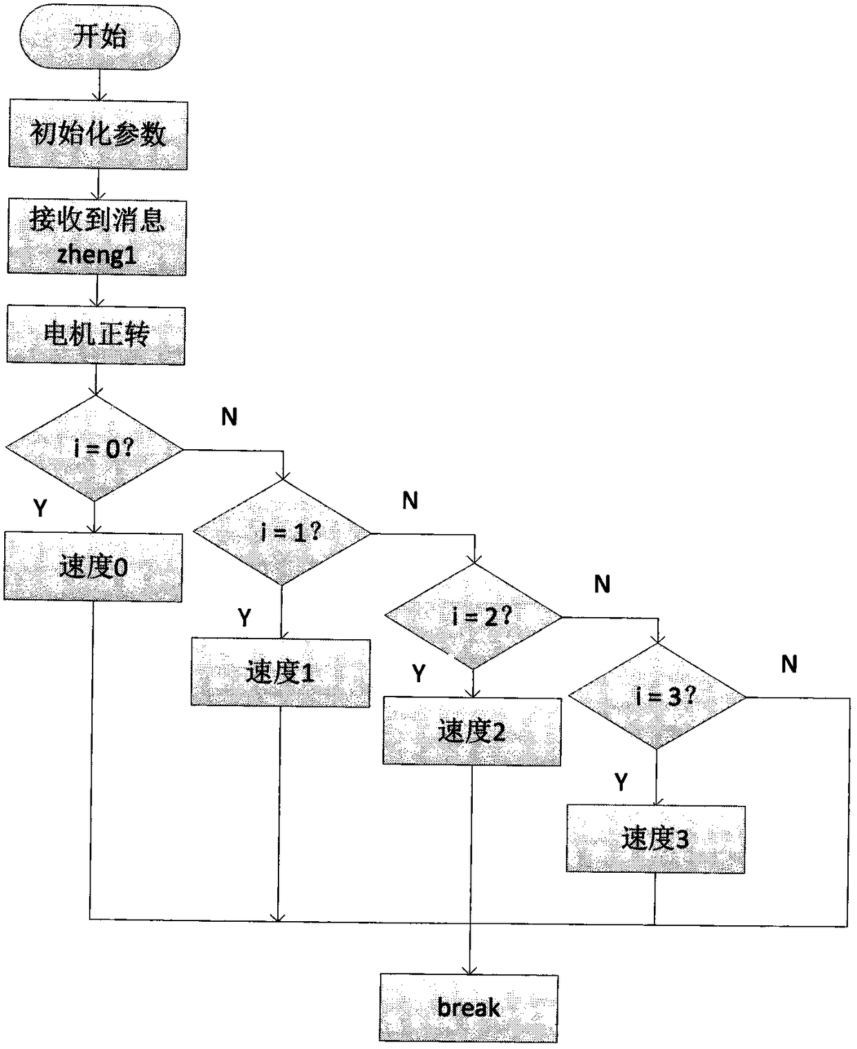
[0023] The remote control mainly sends command signals from the processor, and transmits them to the control module through the wireless module to control the forward and reverse rotation of the DC motor, thereby driving the adjustment of optical parameter conditions and adjusting the optical measurement parameter...


PUM


Abstract

The invention mainly studies the adjustment of the measuring parameters of an optical calibrator in a wireless control mode, so as to realize the function of efficiently measuring an optical sample. In an experiment, the software of DC motor speed regulating system is based on Basic RF provided by TI to receive and transmit data, The hardware is connected with a L298N drive module between the control module and the DC motor. The wireless remote control board sends data to the CC2530 control board to drive the DC motor to rotate and adjust the speed, which is an important application of controlling and adjusting the optical measurement environment in the optical calibrator. The experiment shows that the DC motor speed control system based on L298N can achieve the purpose of wireless controland adjustment of the optical calibrator, which makes the optical calibrator more accurate and efficient in measuring samples.

Description

technical field [0001] The invention relates to a DC motor speed regulation system based on an L298N drive circuit and its application in optical detection instruments, belonging to the field of optical equipment applications. Background technique [0002] With the rapid development of optical processing, precision machinery manufacturing and other industries, the processing requirements for micron / nano-scale surface shapes are getting higher and higher, and the requirements must be 100% non-destructive (that is, non-contact), fast, quantitative, high-precision and The inspection methods and calibration instruments with strong interference performance also put forward higher and higher requirements for the detection technology of nanometer precision. [0003] In the nano-precision detection technology, high-precision optical measurement technology has gradually become one of the most accurate and widely used high-precision measurement methods due to its high sensitivity, hig...

Claims


Application Information

Patent Timeline
Patent Type & Authority Applications(China)
IPC IPC(8): H02P7/18
CPCH02P7/18H02P7/04
Inventor 戴文战吴传良李静
Owner ZHEJIANG GONGSHANG UNIVERSITY
Learn More