

Novel tensioning device
A tensioning device, a new type of technology, is applied in the directions of transportation and packaging, winding strips, thin material processing, etc. It can solve the problems of uneven speed of the rotating shaft, unevenness of the forming belt core, and uneven laying of the canvas, etc., to achieve structural simple effect
Inactive Publication Date: 2014-05-28
YANGZHOU DONGXING RUBBER
View PDF0 Cites 0 Cited by
- Summary
- Abstract
- Description
- Claims
- Application Information
AI Technical Summary
Problems solved by technology
[0002] In the process of forming the belt core of the conveyor belt, the canvas is required to be flat and the elongation is uniform. However, during the actual canvas laying process, due to the uneven speed of the rotating shaft, the canvas laying is not smooth, which leads to the unevenness of the forming belt core.
Method used
View moreImage
Smart ImageViewing Examples

Examples
Embodiment Construction
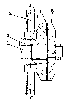
[0008] A new type of tensioning device, including a main shaft 1, a main shaft box 2, and a hand turntable 3. The main shaft 1 is socketed in the main shaft box 2. The right end of the main shaft box 2 is sleeved with a movable static friction plate 4, and the right end of the main shaft 1 is fixed. The dynamic friction plate 5 is connected to the right side of the static friction plate 4, and the brake pad 6 is arranged between the static friction plate 4 and the dynamic friction plate 5. Bearings are arranged between the box 2 radially.
Login to View More PUM
 Abstract
The invention relates to a novel tensioning device which comprises a spindle, a spindle box and a hand rotating plate. The spindle connectedly sleeves in the spindle box, a movable static friction plate connectedly sleeves the right end of the spindle box, a kinetic friction plate fixedly connectedly sleeves the right end of the spindle and is positioned on the right of the static friction plate, a brake pad is arranged between the static friction plate and the kinetic friction plate, the hand rotating plate sleeves the right end of the spindle box in a threaded connection manner and contacts with the left side of the static friction plate, and a bearing is radially arranged between the spindle and the spindle box. The novel tensioning device is simple in structure and capable of adjusting rotating speed of the spindle so as to adjust cloth release tensity.
Description
technical field [0001] The invention relates to a novel tensioning device. Background technique [0002] In the process of forming the belt core of the conveyor belt, the canvas is required to be flat and the elongation is uniform. However, during the actual canvas laying process, due to the uneven speed of the rotating shaft, the canvas laying is uneven, resulting in the formation of the belt core. Contents of the invention [0003] In view of the above defects, the object of the present invention is to provide a novel tensioning device with simple structure and capable of adjusting the tension of cloth release. [0004] For this reason, the technical solution adopted by the present invention is: including a main shaft, a main shaft box, and a hand turntable. Located on the right side of the static friction plate, there is a brake pad between the static friction plate and the dynamic friction plate, the hand turntable is threaded on the right end of the spindle box and c...
Claims
Login to View More Application Information
Patent Timeline
 IPC IPC(8): B65H23/14
Inventor秦焕地
OwnerYANGZHOU DONGXING RUBBER