Method for relief-grinding the cutting teeth of taps, thread formers, and similar tools, and grinding machine for carrying out said method

A technology for forming tools and cutting teeth, which is applied in the direction of grinding machines, manufacturing tools, and other manufacturing equipment/tools, etc., which can solve the problems of time-consuming reassembly and replacement process, and the unresolved problem of replacement parts inventory.

Active Publication Date: 2009-08-05
ERWIN JUNKER MASCHNINENFAB
View PDF2 Cites 4 Cited by
  • Summary
  • Abstract
  • Description
  • Claims
  • Application Information

AI Technical Summary

Problems solved by technology

[0006] Therefore, for the machine according to DE 29 52 610 C2, there is still the disadvantage of time-consuming reassembly and replacement processes together with the problem of stocking high-precision replacement parts.

Method used


Image

  • Method for relief-grinding the cutting teeth of taps, thread formers, and similar tools, and grinding machine for carrying out said method
  • Method for relief-grinding the cutting teeth of taps, thread formers, and similar tools, and grinding machine for carrying out said method
  • Method for relief-grinding the cutting teeth of taps, thread formers, and similar tools, and grinding machine for carrying out said method

Examples


Embodiment Construction

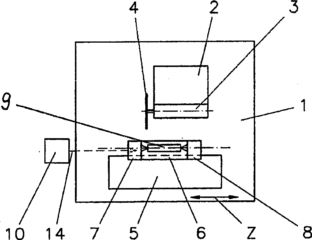
[0023] in accordance with figure 1 In the shown machine, a grinding wheel head 2 is provided on a bed 1, on which a grinding wheel spindle 3 with a rotating grinding wheel 4 is mounted, and the grinding wheel head 2 can also be pivoted about a vertical axis.

[0024] The bed 1 also carries a grinding table 5 which, as is usual, can be adjusted along its longitudinal direction (Z-axis). On the grinding table 5 there is a movable support part 6 which can be additionally adjusted on the grinding table 5 perpendicular to the Z-axis, ie in the usual direction of the X-axis. The supporting part 6 carries a headstock 7 and a tailstock 8 between which, for example, a tap or similar tool 9 can be clamped. The tool 9 that is present here is also the workpiece. The tool is thus likewise extendable along the Z-axis and at the same time controllably rotatable about its longitudinal axis, ie generally the C-axis.

[0025] In the exemplary embodiment shown, the plane of rotation of the gr...


PUM


Abstract

In prior art, an additional radial inward movement that is performed in accordance with a rotating cam disk is imparted on the grinding disk in order to relief-grind the cutting teeth and the chamfer of taps and the cutting teeth of thread formers. The invention relates to a cam disk (11) which can be rotated about an axis A and is provided with a control cam (12). Said control cam (12) forms a group of curves according to a large number of possible undercut contours on the grinding teeth of the tap or thread former, which are to be relief-ground. In order to obtain a specific undercut contour on a cutting tooth, a limited angle of rotation alpha is selected from the control cam (12). Said area is mechanically, optically, or electronically scanned by means of a scanning device (13). To this avail, the cam disk (11) performs an oscillating rotary movement only above the selected section of the control cam (12) (arrow indicating the direction of rotation 15). Relief-grinding of the cutting tooth is completed once a fore-and-aft movement has been performed, and the grinding disk returns to the starting position thereof. The result of the scan is transmitted to an electronic control device via a signal line (14).

Description

technical field [0001] The invention relates to a method for relief grinding of cutting teeth of taps or thread forming tools or similar tools according to features a to d of claim 1, wherein the term "cutting teeth" shall also include threads Contour forming tools for forming tools. Background technique [0002] Such methods belong to the prior art. [0003] A device for this purpose is proposed, for example, in CH-PS 413 637, in which the control shaft always turns in the same direction. Two identically constructed control disks with cams are arranged on the control shaft. The cams of the two control disks are offset from each other by 180 degrees. On each control disk there is a tapping roller, which are coupled to one another via a parallelogram lever system. The scanning movement of the coupling roller is transferred to the eccentric bearing of the grinding shaft via an additional lever system. The eccentric bearing of the grinding shaft is rotated according to the...

Claims


Application Information

Patent Timeline
Patent Type & Authority Applications(China)
IPC IPC(8): B24B3/22B24B17/02B23Q35/10
CPCB24B3/22B24B17/025B24B3/022
Inventor 埃尔温·容克尔
Owner ERWIN JUNKER MASCHNINENFAB
Why Eureka
Try Eureka