Hydraulic actuator and compound rocker arm

A technology of hydraulic actuation and hydraulic oil, applied in the direction of fluid pressure actuation device, transmission device, fluid transmission device, etc.

Inactive Publication Date: 2015-11-04
孙晓君
View PDF6 Cites 13 Cited by
  • Summary
  • Abstract
  • Description
  • Claims
  • Application Information

AI Technical Summary

Problems solved by technology

In the existing mechanical structure, there is no mechanical device that realizes that the first type of output moti...

Method used


Image

  • Hydraulic actuator and compound rocker arm
  • Hydraulic actuator and compound rocker arm

Examples


Embodiment Construction

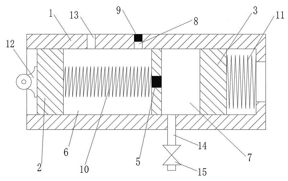
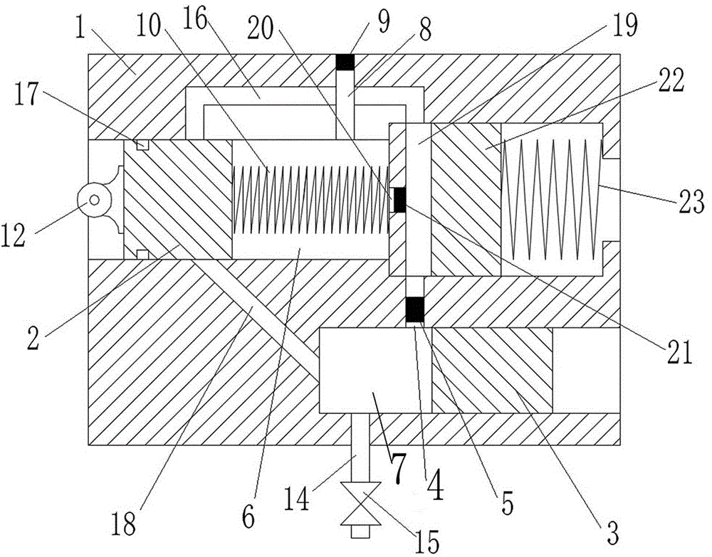
[0025] Attached below figure 1 , attached figure 2 The present invention will be further described.

[0026] A hydraulic actuator, comprising: a housing 1, which is divided into two mutually independent chambers I 6 and chamber II 7, and the chamber I 6 and chamber II 7 are communicated through the oil delivery channel I 4 ;Input piston 2, which is slidably installed in cavity I 6; output piston 3, which is slidably installed in cavity II 7, oil inlet 8, which is arranged on cavity I 6, and communicated with cavity I 6 , the input piston 2 will not close the oil inlet 8 during the sliding stroke in the chamber I 6; the oil return port 14, which is arranged on the chamber I 6, communicates with the chamber II 7, and the oil return port 14 There is a control valve 15 on the top, the output piston 3 will not close the oil return port 14 during the sliding stroke of the cavity II 7; and a delay mechanism, the delay mechanism makes the input piston 2 after a certain delay during...


PUM


Abstract

The invention relates to a hydraulic actuator and a compound rocker arm. The hydraulic actuator comprises a shell, an input piston, an output piston, an oil return opening and a time-delay mechanism, wherein the shell is divided into two mutually independent cavities, namely the cavity I and the cavity II. When a mechanical driving mechanism which conducts input motion drives the input piston to move to the inner side end, the time-delay mechanism controls hydraulic oil in the cavity I not to flow into the cavity II within a certain time, and after a certain time delay, the hydraulic oil in the cavity I flows into the cavity II through an oil conveying pipeline I via a one-way valve, so that the output piston is pushed to move, and the output piston drives an output driven object to move after time delay. A control valve mainly has the function of adjusting the moment when the output piston starts to reset, and meanwhile the reset speed of the output piston can be adjusted. By means of the hydraulic actuator, in the case of one original motive mechanism, controllable changes of motion moments and motion rules of multiple output motion mechanism phases controlled through the output piston are achieved.

Description

technical field [0001] The invention relates to a hydraulic actuator and a composite rocker arm. Background technique [0002] A type of periodic cyclic mechanical motion includes a motive input and multiple output motion relationships. Multiple outputs are divided into two types according to different driving target requirements. The relationship between the first type of output and input motion is a direct lever or cam. The second type requires a part of the input energy to be temporarily stored by the energy storage link, and the energy storage link is triggered to release energy under specific conditions and opportunities, thereby indirectly driving the second type of target to complete the movement. The second type of output cyclic motion maintains a specific output state, and then resets itself according to its inherent time parameters and returns to the initial state, or is controlled by a specific external signal, and the self-resetting feature does not depend on the...

Claims


Application Information

Patent Timeline
IPC IPC(8): F15B15/17F15B15/22F15B15/20F15B1/02F15B15/06F16H43/00
CPCF15B1/02F15B15/06F15B15/17F15B15/20F15B15/22F16H43/00
Inventor 孙晓君
Owner 孙晓君
Why Eureka
Try Eureka