Eureka AIR delivers breakthrough ideas for toughest innovation challenges, trusted by R&D personnel around the world.

Electric control anti-blocking butterfly valve

A butterfly valve and electric cylinder technology, applied in the field of electric control anti-blocking butterfly valve, can solve the problems of environmental pollution, dirt blockage, time-consuming and laborious, etc., and achieve the effects of reducing the force-bearing surface, easy control, and realization of automation

Inactive Publication Date: 2015-11-04
天津市精沃阀门科技有限公司
View PDF0 Cites 6 Cited by
  • Summary
  • Abstract
  • Description
  • Claims
  • Application Information

AI Technical Summary

Problems solved by technology

Existing butterfly valves are used in sewage discharge pipelines, which are prone to blockage caused by accumulation of dirt on the valve plate. Whenever blockage occurs, the butterfly valve must be disassembled for cleaning, which takes man-hours and causes sewage to flow across, polluting the environment. At the same time, the butterfly valve The control is to turn the valve shaft by manually pulling the wrench, which is time-consuming and laborious

Method used


Image

  • Electric control anti-blocking butterfly valve
  • Electric control anti-blocking butterfly valve
  • Electric control anti-blocking butterfly valve

Examples


Embodiment Construction

[0025] It should be noted that, in the case of no conflict, the embodiments of the present invention and the features in the embodiments can be combined with each other.

[0026] The present invention will be described in detail below with reference to the accompanying drawings and examples.

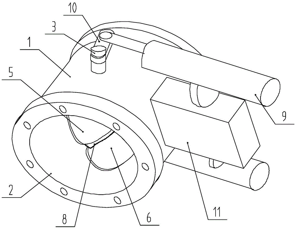
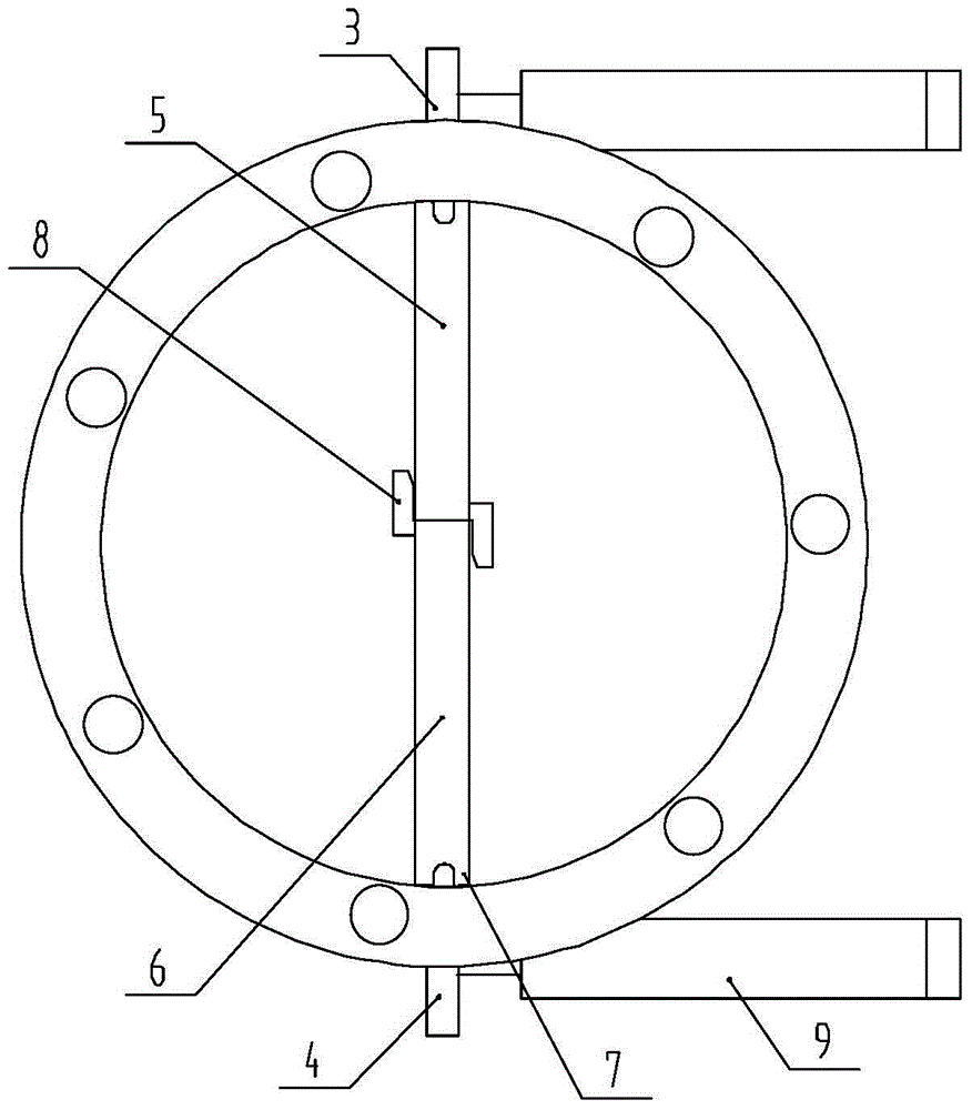
[0027] An electric control anti-blocking butterfly valve, such as figure 1 and figure 2 As shown, it includes a valve body 1 with a cavity, a valve seat 2 installed in the valve body 1, and an upper valve shaft 3 and a lower valve shaft 4 coaxially arranged through the valve body 1 and the valve seat 2; An upper valve plate 5 is fixedly installed on the valve shaft 3, and the upper valve plate 5 rotates in the valve seat 2 around the upper valve shaft 3; a lower valve plate 6 is fixedly installed on the lower valve shaft 4, and the lower valve plate 6 Turn around the lower valve shaft 4 in the valve seat 2, and the lower valve plate 6 can turn to the same plane with the upper valve pl...


PUM


Abstract

The invention provides an electric control anti-blocking butterfly valve. The electric control anti-blocking butterfly valve comprises a valve body with a cavity, a valve seat installed in the valve body, an upper valve shaft and a lower valve shaft, wherein the upper valve shaft and the lower valve shaft penetrate the valve body and the valve seat and are coaxially arranged. An upper valve plate is fixedly installed on the upper valve shaft and rotates in the valve seat around the upper valve shaft. A lower valve plate is fixedly installed on the lower valve shaft and rotates in the valve seat around the lower valve shaft. The lower valve plate and the upper valve plate can rotate to the same plane to be matched with the valve seat to close the butterfly valve. The ends, extending out of the valve body, of the upper valve shaft and the lower valve shaft are provided with an electric execution mechanism. The two valve plates controlled by the electric execution mechanism and opened and closed independently and respectively are arranged, so that time and labor are saved when the opening degree of the valve plates is adjusted, influences of pollutant blockage are avoided, and the blockage phenomenon is avoided. In addition, when the upper valve plate and the lower valve plate are opened and closed independently, stress faces can be reduced, pollutants can be stirred to the maximum extent and scattered, and therefore the pollutant self-removing function is achieved.

Description

technical field [0001] The invention belongs to the technical field of valves, in particular to an electric control anti-blocking butterfly valve. Background technique [0002] Butterfly valves have become one of the most widely used valves at present. Generally, a butterfly valve includes a valve seat, a valve body, a valve shaft, and a valve plate. That is, the valve body has an inner cavity, the valve seat is fixed in the valve body, the valve plate is located in the valve inner cavity, and after the valve plate rotates, its edge and the valve seat are sealed or opened, and the valve stem is used to drive the valve body. The valve plate rotates. Existing butterfly valves are used in sewage discharge pipelines, which are prone to blockage caused by accumulation of dirt on the valve plate. Whenever blockage occurs, the butterfly valve must be disassembled for cleaning, which takes man-hours and causes sewage to flow across, polluting the environment. At the same time, the...

Claims


Application Information

Patent Timeline
Patent Type & Authority Applications(China)
IPC IPC(8): F16K1/22F16K1/226F16K1/36F16K31/04F16K31/52
CPCF16K1/221F16K1/223F16K1/2261F16K31/043F16K31/521
Inventor 李继元刘凯
Owner 天津市精沃阀门科技有限公司
Why Eureka
Eureka Blog
Learn More