Industrial wastewater microfiltration system
A technology of industrial wastewater and microfiltration, which is applied in the direction of filtration circuit, filtration separation, filtration treatment, etc., can solve the problems of microfiltration equipment clogging, poor equipment adaptability, and affecting filtration efficiency, so as to reduce clogging, improve performance, and help Effect on slag discharge
- Summary
- Abstract
- Description
- Claims
- Application Information
AI Technical Summary
Problems solved by technology
Method used
Image
Examples
Embodiment example 1
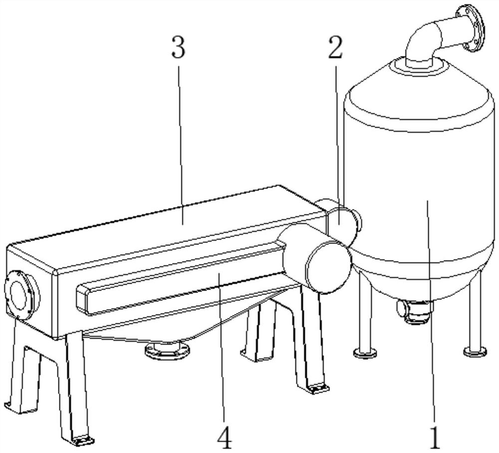
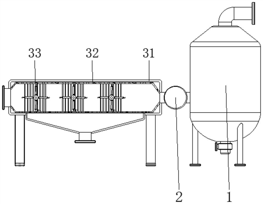
[0029] see Figure 1-6 , the present invention provides a technical solution: an industrial wastewater microfiltration system, including a sedimentation tank 1, a power transmission mechanism 2, a wastewater microfiltration device 3, and a linkage driving mechanism 4, and the power transmission mechanism 2 is arranged on the surface bottom of the sedimentation tank 1 On one side, the wastewater microfiltration device 3 is arranged at the end of the power transmission mechanism 2 away from the sedimentation tank 1, and the linkage drive mechanism 4 is arranged on the surface side of the wastewater microfiltration device 3. 3 are connected;
[0030] The wastewater microfiltration device 3 is provided with a body 31, a filtering device 32, and a rotating device 33. The body 31 is arranged at one end of the power transmission mechanism 2, the filtering device 32 is arranged inside the body 31, and the rotating device 33 is arranged inside the filtering device 32. The device can e...
Embodiment example 2
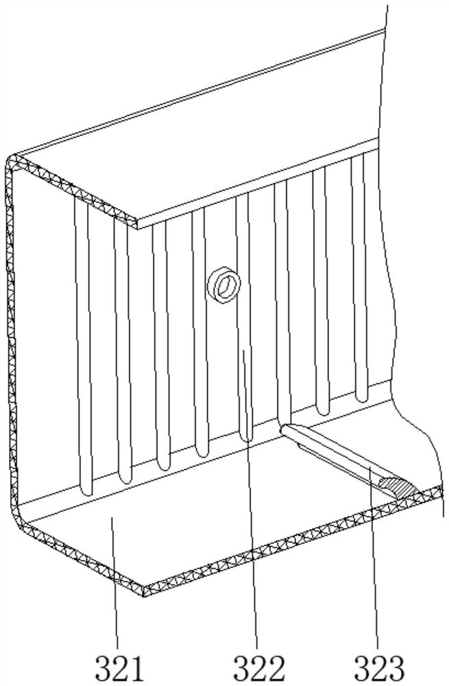
[0032] The filtering device 32 is provided with a square microfilter 321, a bar bar 322, and an arc top bar 323. The surface of the square microfilter 321 is fixedly connected with the inner wall of the body 31, and the bar bar 322 is fixed on two corresponding sides of the square microfilter 321 inner wall. Side, the bar 322 is fixed on the two sides corresponding to the inner wall of the square microfilter 321, and is fixed on the bottom of the inner wall of the square microfilter 321 and close to the position of the rotating device 33, and uses the power transmission mechanism 2 to transport the settled waste water to the square microfilter. In the filter 321, the waste water is micro-filtered, and at the same time, the bar 322 supports the square micro-filter 321, so that its own strength is high, and it is not easy to bend or deform. At the same time, it can also exert a blocking effect on the rotating elastic toggle device 334, It can self-clean the side wall of the squar...
Embodiment example 3
[0034] The rotating device 33 is provided with a rotating roller 331, a blade 332, a beating device 333, and an elastic toggle device 334. The rotating roller 331 is arranged inside the filter device 32, and the ends of the rotating roller 331 pass through the inner wall of the filter device 32 and the body 31 successively. The inner wall extends to the outside of the body 31 and cooperates with the linkage drive mechanism 4. The blade 332 is fixed on the surface of the rotating roller 331 and is located at the central position. The striking device 333 is arranged inside the blade 332 and located at the end position. The elastic driving device 334 is disposed on the surface of the rotating roller 331 and located on two sides corresponding to the blade 332 .
[0035]The hitting device 333 is provided with a slide bar 3331, a return spring 3332, and a bumper ball 3333. The slide bar 3331 is slidably connected to the inside of the blade 332 and is located at the end position. The ...
PUM
 Abstract
Description
Claims
Application Information
 - R&D
- Intellectual Property
- Life Sciences
- Materials
- Tech Scout
- Unparalleled Data Quality
- Higher Quality Content
- 60% Fewer Hallucinations
Browse by: Latest US Patents, China's latest patents, Technical Efficacy Thesaurus, Application Domain, Technology Topic, Popular Technical Reports.
© 2025 PatSnap. All rights reserved.Legal|Privacy policy|Modern Slavery Act Transparency Statement|Sitemap|About US| Contact US: help@patsnap.com


