led dimming circuit

A dimming circuit and LED driving technology, applied in the direction of lamp circuit layout, light source, electric light source, etc., can solve the problems of mismatching, high cost, low efficiency, etc.

Active Publication Date: 2017-11-10
GUANGDONG WISTECH ENERGY SAVING TECH
View PDF4 Cites 0 Cited by
  • Summary
  • Abstract
  • Description
  • Claims
  • Application Information

AI Technical Summary

Problems solved by technology

[0004] The embodiment of the present invention proposes an LED dimming circuit, which can effectively solve the problem of poor dimming linearity, poor consistency, low efficiency, low power factor, high cost, and incompatibility with the original user lines in existing dimming circuits. There are special requirements for new subscriber lines, etc.

Method used


Image

  • led dimming circuit
  • led dimming circuit
  • led dimming circuit

Examples


Embodiment Construction

[0035] The following will clearly and completely describe the technical solutions in the embodiments of the present invention with reference to the accompanying drawings in the embodiments of the present invention. Obviously, the described embodiments are only some, not all, embodiments of the present invention. Based on the embodiments of the present invention, all other embodiments obtained by persons of ordinary skill in the art without creative efforts fall within the protection scope of the present invention.

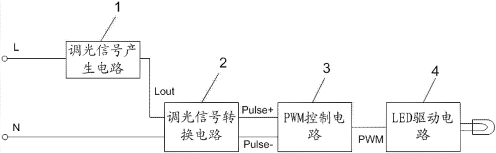
[0036] see figure 1 , is a structural block diagram of an LED dimming circuit provided by an embodiment of the present invention, which includes a dimming signal generating circuit 1 , a dimming signal converting circuit 2 , a PWM control circuit 3 and an LED driving circuit 4 .

[0037] The dimming signal generating circuit 1 has a live wire signal input terminal L and a dimming signal output terminal Lout; the dimming signal conversion circuit 2 has a dimming sig...


PUM


Abstract

The invention discloses an LED dimming circuit, comprising a dimming signal generating circuit, a dimming signal conversion circuit, a PWM control circuit and an LED drive circuit; the dimming signal generating circuit is used to generate a dimming signal; the dimming The signal conversion circuit is used to receive the neutral line signal and the dimming signal output by the dimming signal generating circuit, and generate a first square wave signal and a second square wave signal according to the neutral line signal and the dimming signal; The PWM control circuit is used to adjust the duty cycle of the PWM signal and output it to the LED drive circuit according to the first square wave signal and the second square wave signal; the LED drive circuit is used to adjust the duty cycle of the PWM signal according to the PWM The signal drives the LED to emit light. The brightness of the LED lighting is controlled by a single live wire, no remote control is required, no control wires are required, and no power lines need to be re-laid. It can replace and upgrade ordinary lighting, with low cost and strong anti-interference ability.

Description

technical field [0001] The invention relates to the technical field of LEDs, in particular to an LED dimming circuit. Background technique [0002] Because of the strict control of the working voltage and current of LED lamps to meet the requirements of its working characteristics, reliability and high efficiency, general LED lamps need to be equipped with a dedicated driving power supply. And users also have different requirements for the illumination of the light source at different times; for example, sometimes we need the lamp to work at the maximum brightness to meet our need for contrast illumination, and sometimes we need it to reduce the brightness to meet our need for weaker fill light. Requirements, but also save power consumption. Therefore, the dimming control of LED lamps can also contribute to the prevention of global warming while meeting more needs of users; and because of the user's requirements for dimming LED lamps: it has excellent linearity and a wide d...

Claims


Application Information

Patent Timeline
Patent Type & Authority Patents(China)
IPC IPC(8): H05B37/02
Inventor 傅强李云张国峥陆东阳罗隽灏
Owner GUANGDONG WISTECH ENERGY SAVING TECH
Why Eureka
Try Eureka