Power conversion device

A power conversion device and power conversion technology, applied in emergency protection circuit devices, output power conversion devices, electrical components, etc., can solve problems such as inflow of excessive current, achieve guaranteed action characteristics, fast action response, and simplify the overall structure effect

Active Publication Date: 2015-11-04
FUJI ELECTRIC CO LTD
View PDF12 Cites 3 Cited by
  • Summary
  • Abstract
  • Description
  • Claims
  • Application Information

AI Technical Summary

Problems solved by technology

[0007] However, during the period until the failed power conversion unit 2 (2a to 2n) is disconnected by the switch 7, the other sound power conversion units 2 (2a to 2n) are transferred to the failed power conversion unit 2. (2a~2n) short-circuit points flow excessive current
Then, there is a possibility that other healthy power conversion units 2 ( 2 a to 2 n ) will fall into an overcurrent state due to the inflow of the excessive current.

Method used


Image

  • Power conversion device
  • Power conversion device
  • Power conversion device

Examples


Embodiment Construction

[0024] Hereinafter, a power conversion device according to an embodiment of the present invention will be described with reference to the drawings.

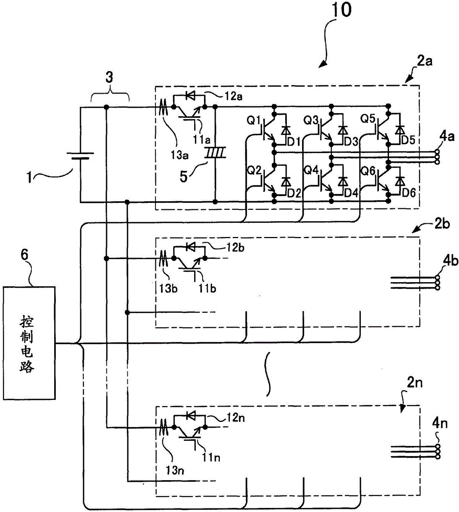
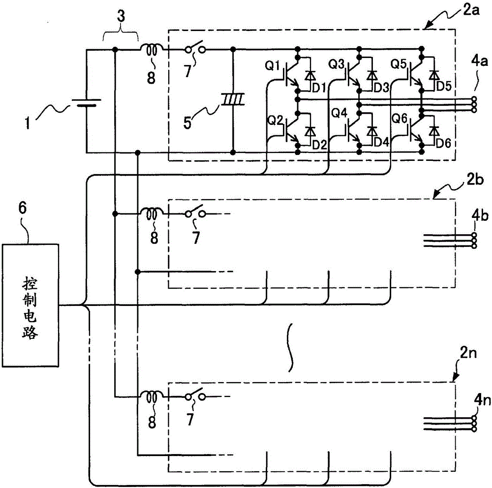
[0025] figure 1 is a diagram showing a schematic configuration of main parts of a power conversion device 10 according to an embodiment of the present invention, and image 3 The same parts of the shown conventional power conversion device are denoted by attaching the same symbols. In addition, overlapping descriptions of these constituent elements shown with the same reference numerals are omitted. In addition, the above-mentioned DC power supply unit 1 in this embodiment is implemented as a voltage-controlled PWM converter or the like that uses semiconductor switching elements such as IGBTs and MOS-FETs to switch a DC input voltage to generate a predetermined DC output voltage.

[0026] In addition, the power conversion device 10 of this embodiment is characterized in that semiconductor switching elements 11 ( 11 a to 11 n ) ...


PUM


Abstract

Semiconductor switching elements are individually inserted between a plurality of power conversion units provided in parallel with each other through a DC link portion and a DC power supply unit for supplying DC power to each of the power conversion units and limit DC powers supplied to the respective power conversion units. A control circuit monitors short-circuit current occurring in each of the power conversion units and turns off the semiconductor switching element connected to a power conversion unit in which short-circuit current has flowed to interrupt the power supplied to said power conversion unit.

Description

technical field [0001] The present invention relates to a power conversion device capable of rapidly disconnecting a failed power conversion unit among a plurality of power conversion units installed in parallel from a DC power supply unit that supplies DC power to each of the power conversion units, so that Other sound power conversion units continue to operate. Background technique [0002] As a power supply device that drives a large-capacity AC load such as a motor using a DC power supply as a power source, or drives a plurality of AC loads in parallel, a power conversion device in which a plurality of power conversion units are connected in parallel is used. image 3 1 is a schematic configuration diagram of such a power conversion device, and 1 is a DC power supply unit. The DC power supply unit 1 is composed of, for example, a diode circuit for rectifying and smoothing commercial AC power, a battery, and the like. [0003] In addition, 2 ( 2 a to 2 n ) is a plurality...

Claims


Application Information

Patent Timeline
Patent Type & Authority Applications(China)
IPC IPC(8): H02M7/48
CPCH02M7/48H02H7/1225H02M2001/008H02M2001/325H02M1/008H02M1/325H02M5/458
Inventor 田久保扩
Owner FUJI ELECTRIC CO LTD
Why Eureka
Try Eureka