Self-sinking type slag filtering device of slag conveyor

A self-sinking, slag removing machine technology, applied in mechanical cleaning, manufacturing tools, metal processing equipment, etc., can solve the problems of cost increase, slag clogging, failure to separate slag and iron, etc., to maintain stability and reliability, The filter residue effect remains stable and ensures the effect of the filter residue effect

Active Publication Date: 2015-11-11
YANTAI SHENGLIDA ENG TECH
View PDF6 Cites 0 Cited by
  • Summary
  • Abstract
  • Description
  • Claims
  • Application Information

AI Technical Summary

Problems solved by technology

The slag removal methods in the prior art include: (1) using steel plates or steel castings without holes as the slag removal rake, the disadvantage is that the slag and iron cannot be separated in time and effectively, and part of the residue will flow away with the molten iron; (2) ) using a slag rake with holes, although the separation of slag and iron can be achieved in the early stage of use, but due to the erosion of high-temperature molten iron, the holes expand rapidly and cause slag leakage, or are blocked by slag and lose their effect; (3) replaceable filter As a filter device, the screen also has the problem of hole expansion and blockage. After a period of use, the filter screen needs to be replaced, resulting in increased maintenance workload and increased costs.

Method used


Image

  • Self-sinking type slag filtering device of slag conveyor
  • Self-sinking type slag filtering device of slag conveyor
  • Self-sinking type slag filtering device of slag conveyor

Examples


specific Embodiment 1

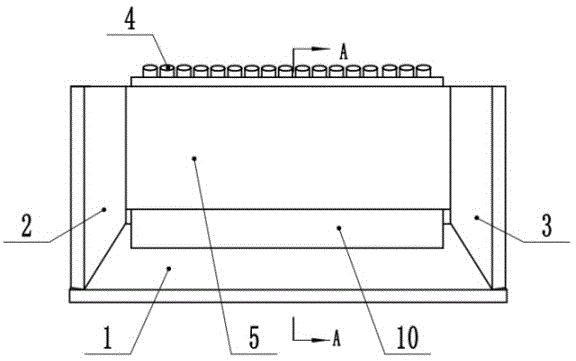
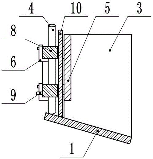
[0033] like Figures 1 to 3 , each upright bar 4 is individually movable and installed in the positioning groove of the grid bracket 8 to ensure that the upright bar 4 can sink freely when gravity or external force impacts, so as to ensure that the bottom end of each upright bar 4 is always in contact with the bottom plate 1 ; The present embodiment also includes a vertical plate 5 located inside the grid, the front and rear ends of the vertical plate 5 are connected to the front end plate 2 and the rear end plate 3 respectively, and the lower edge of the vertical plate 5 is connected to the bottom plate 1 There is a gap between them; the grid support 8 is fixed on the vertical plate 5 through the card slot 6. The bottom plate 1 , the front end plate 2 , the rear end plate 3 and the vertical plate 5 form a slag filter device in the form of a slag rake with openings on the inner surface and the upper end surface.

[0034] On the inner side of the grid, there is also a slag ret...

specific Embodiment 2

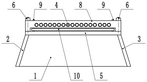
[0039] like Figure 4-6 , the vertical bar 4 is fixed on the grille bracket 8, and the grille is installed in the vertical guide groove to ensure that the grille can sink freely when the gravity or external force is impacted, so as to always ensure that the bottom end of the grille keeps in contact with the bottom plate 1; The vertical guide grooves are arranged on the front end plate 2 and the rear end plate 3 . The bottom plate 1 , the front end plate 2 , the rear end plate 3 and the grille form a slag filter device in the form of a slag rake whose inner side and upper end are open.

[0040] In order to ensure the strength of the device at high temperature, a number of reinforcing plates 7 are also arranged between the front end plate 2 and the rear end plate 3 . The front and rear ends of the reinforcing plate 7 are connected with the front end plate 2 and the rear end plate 3 respectively.

[0041] A slag baffle 10 that can be quickly melted by molten iron is also arrang...

specific Embodiment 3

[0046] The specific embodiment 2 may also include a vertical plate located on the inner side of the grill, the front and rear ends of the vertical plate are respectively connected to the front end plate and the rear end plate, and there is a gap between the lower edge of the vertical plate and the bottom plate. The bottom plate, the front end plate, the rear end plate and the vertical plate enclose a slag filter device in the form of a slag rake whose inner side and upper end face are open.


PUM

PropertyMeasurementUnit
thicknessaaaaaaaaaa

Abstract

The invention provides a self-sinking type slag filtering device of a slag conveyor. The self-sinking type slag filtering device mainly comprises a bottom plate (1), a front end plate and a rear end plate (3), wherein the front end plate and the rear end plate (3) are fixedly connected to the front end and the rear end of the bottom plate (1) respectively. The self-sinking type slag filtering device further comprises a grid located above the bottom plate (1) and between the front end plate and the rear end plate (3). The grid comprises a grid support (8) and a plurality of vertical strips (4). The vertical strips (4) are independently and movably installed in positioning grooves of the grid support (8). The side faces of the vertical strips (4) are coated with a fireproof and slag bonding preventing coating. By means of the device for slag filtering, molten iron can be filtered through gaps of the grid, the slag filtering efficiency is high, and the effect is good. Meanwhile, after the lower ends of the vertical strips (4) are molten, the vertical strips (4) can automatically sink under the effect of gravity and impact vibration, and it is ensured that the bottoms of the vertical strips (4) make contact with the bottom plate (1) all the time. The slag filtering effect is stable, and reliability is high. The slag filtering device does not need to be frequently replaced, and the maintaining workload is small.

Description

technical field [0001] The invention relates to a slag filter device of a slag extractor, belonging to the field of metallurgical equipment. It is mainly used for slag removal of molten iron in iron and steel enterprises, and can also be used for other solid-liquid separation operations of horizontal filtration. Background technique [0002] The function of the molten iron slag extractor is mainly to remove the scum in the molten iron and realize the solid-liquid separation of the scum and the molten iron. The slag removal methods in the prior art include: (1) using steel plates or steel castings without holes as the slag removal rake, the disadvantage is that the slag and iron cannot be separated in time and effectively, and part of the residue will flow away with the molten iron; (2) ) using a slag rake with holes, although the separation of slag and iron can be achieved in the early stage of use, but due to the erosion of high-temperature molten iron, the holes expand ra...

Claims


Application Information

Patent Timeline
Patent Type & Authority Applications(China)
IPC IPC(8): B22D43/00
Inventor 盛镝
Owner YANTAI SHENGLIDA ENG TECH
Why Eureka
Try Eureka