
Lithium niobate wafer grinding device and grinding method with grinding pressure adjustment device

A grinding pressure and adjusting device technology, which is applied in the direction of grinding devices, grinding machine tools, working carriers, etc., can solve the problems of inability to adjust the pressure accurately, unsatisfactory, uneven grinding of the end face of the optical fiber, etc., and achieve intuitive and reliable adjustment and excellent grinding quality. equal effect

Inactive Publication Date: 2017-06-06
BEIHANG UNIV
View PDF7 Cites 0 Cited by
  • Summary
  • Abstract
  • Description
  • Claims
  • Application Information

AI Technical Summary

Problems solved by technology

One of the existing grinding machines is to manually release a weight of corresponding quality to adjust the pressure, and the other is to use a pneumatic device to centrally pressurize the fiber ferrule or bare optical fiber: neither of these two pressurization methods can Accurately adjust the size of the pressure. The research on the influence of the grinding pressure on the grinding of the fiber ferrule or bare fiber is not thorough. Improper grinding pressure may cause uneven grinding of the fiber end face, making it difficult to meet the requirements of low coupling loss.
And for optical fiber polishing products with special angle requirements, due to the low precision of the manufactured ferrule, it cannot meet the given index

Method used


Image

  • Lithium niobate wafer grinding device and grinding method with grinding pressure adjustment device
  • Lithium niobate wafer grinding device and grinding method with grinding pressure adjustment device
  • Lithium niobate wafer grinding device and grinding method with grinding pressure adjustment device

Examples


Embodiment Construction

[0056] The present invention will be described in further detail below in conjunction with the accompanying drawings.

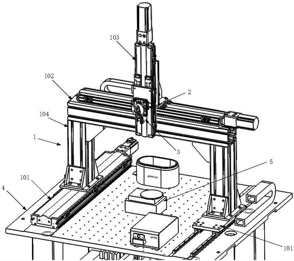
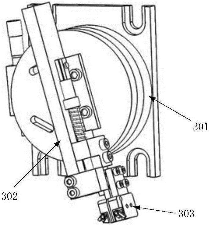
[0057] The present invention has the lithium niobate wafer grinding device of grinding pressure adjustment device, as figure 1 As shown, it includes a three-dimensional space positioning device 1 , a beam force sensor 2 and a grinding and clamping mechanism 3 .

[0058] The three-dimensional spatial positioning device 1 is set on the grinding platform 4 and adopts a door-shaped design, including two sets of x-axis moving mechanisms 101 , one set of y-axis moving mechanisms 102 , one set of z-axis moving mechanisms 103 and two pillars 104 . The x-axis moving mechanism 101 and the y-axis moving mechanism 102 are structurally the same as the z-axis moving mechanism 103, and are composed of a mounting table, a slide rail, a slide table, a ball screw and a driving motor. Wherein, two slide rails parallel to each other are installed on the mounting table. The scr...


PUM


Abstract

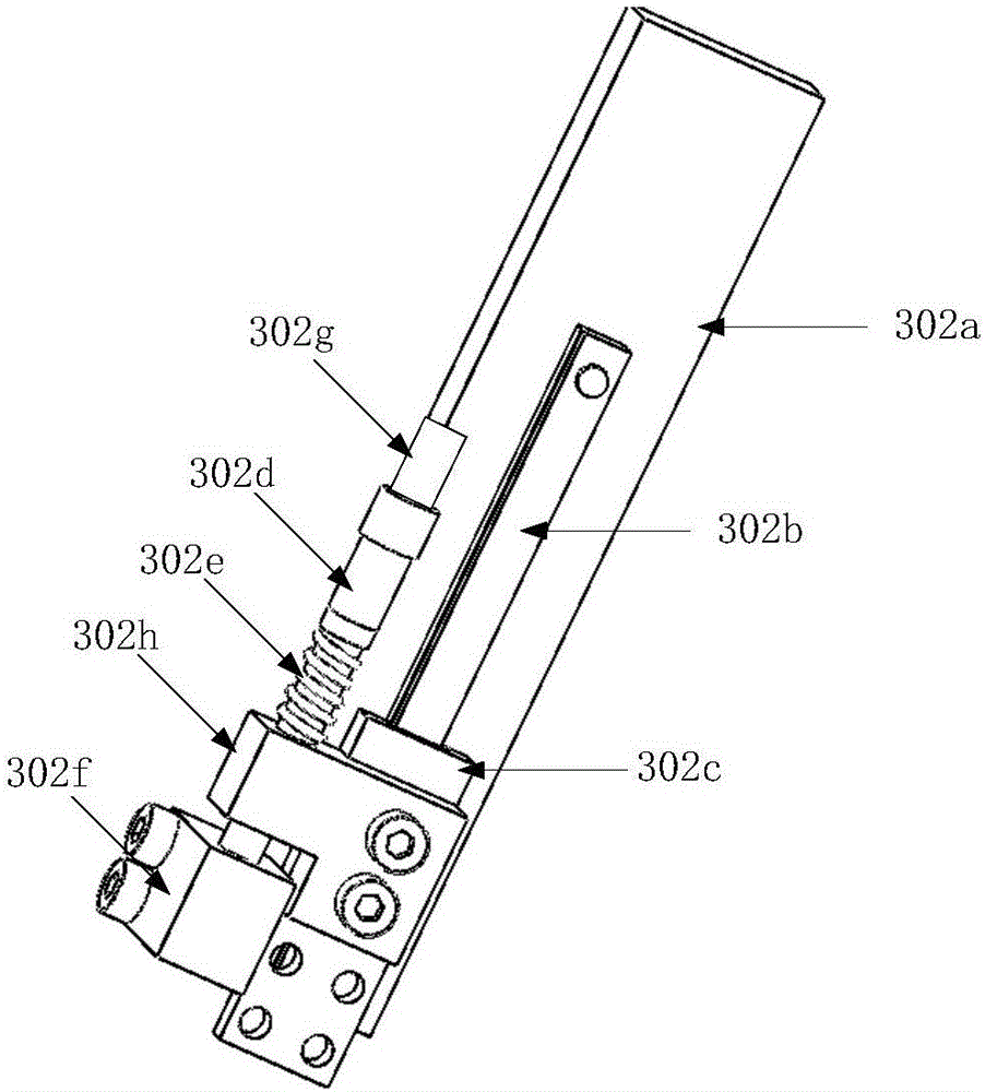
The invention discloses a lithium niobate wafer grinding device with a grinding pressure adjusting device and a grinding method. The grinding device comprises a three-dimensional space positioning device, a beam type force sensor and a grinding and clamping mechanism. The three-dimensional space positioning device is provided with the grinding and clamping mechanism through a force sensor, and two lithium niobate wafers clamped by the grinding and clamping mechanism are positioned at any point in the space. A clamping mechanism of the grinding and clamping mechanism is installed on a sliding block in the grinding pressure adjusting device in a sliding manner. A calibrated adjusting screw with a read head is adopted in the grinding pressure adjusting device, and adjustment of the pressure between the lithium niobate wafers and a grinding table is achieved in the grinding process. During grinding, the distances between contact points of the two lithium niobate wafers and a grinding machine and a main shaft of the grinding machine need to be equal. The lithium niobate wafer grinding device has the beneficial effects that the calibrated adjusting screw with the read head is adopted, and adjustment of the grinding pressure is visual and reliable; and during grinding, a positioning manner of the two lithium niobate wafers is adopted, and the grinding mass of the two lithium niobate wafers is the same.

Description

technical field [0001] The invention relates to a grinding device, which belongs to the technical field of optical fiber grinding, in particular to a lithium niobate wafer grinding device and a grinding method with a grinding pressure adjustment device. Background technique [0002] At present, in the production process of high-precision closed-loop fiber optic gyroscope, the direct connection method of the end face has gradually become the mainstream method of coupling the Y waveguide and the polarization-maintaining fiber chip. In order to facilitate grinding and coupling, the pigtail is generally bonded to a lithium niobate wafer before grinding, and the pigtail and the lithium niobate wafer are ground and polished together. If the grinding parameters are not properly controlled during pigtail grinding, a large number of microcracks will be generated on the end face of the fiber, resulting in high roughness of the end face of the fiber, and the insertion loss will increas...

Claims


Application Information

Patent Timeline
Patent Type & Authority Patents(China)
IPC IPC(8): B24B37/10B24B37/30B24B37/005B24B37/34
CPCB24B37/005B24B37/107B24B37/30B24B37/34
Inventor 李慧鹏张轩朱伟伟郑晓宋凝芳高爽
Owner BEIHANG UNIV
Learn More