
An acousto-optic q switch and laser device

An acousto-optic and switching technology, applied in the laser field, can solve problems such as poor stability, large space for fixing the collimator, cumbersome dimming, etc., and achieve the effect of reducing the number of dimming times and making dimming simple and convenient

Active Publication Date: 2019-02-05
SHENZHEN SUPER LASER TECH
View PDF8 Cites 0 Cited by
  • Summary
  • Abstract
  • Description
  • Claims
  • Application Information

AI Technical Summary

Problems solved by technology

[0004] In the existing acousto-optic Q switch, since the light from the collimator is collimated light, an adjustment frame is usually required to adjust the deflection angle of the collimator so that the light emitted from the collimator enters the acousto-optic light at the Bragg angle. In the crystal, the Bragg diffraction requirements of the acousto-optic crystal to the light can be met. However, in the above method, because the deflection angle of the collimator needs to be adjusted, the light adjustment is more cumbersome, and a space for adjusting the angle needs to be reserved, so the collimator The fixed space is large and the stability is not good

Method used


Image

  • An acousto-optic q switch and laser device
  • An acousto-optic q switch and laser device
  • An acousto-optic q switch and laser device

Examples


Embodiment Construction

[0023] The present invention will be described in detail below with reference to the drawings and embodiments.

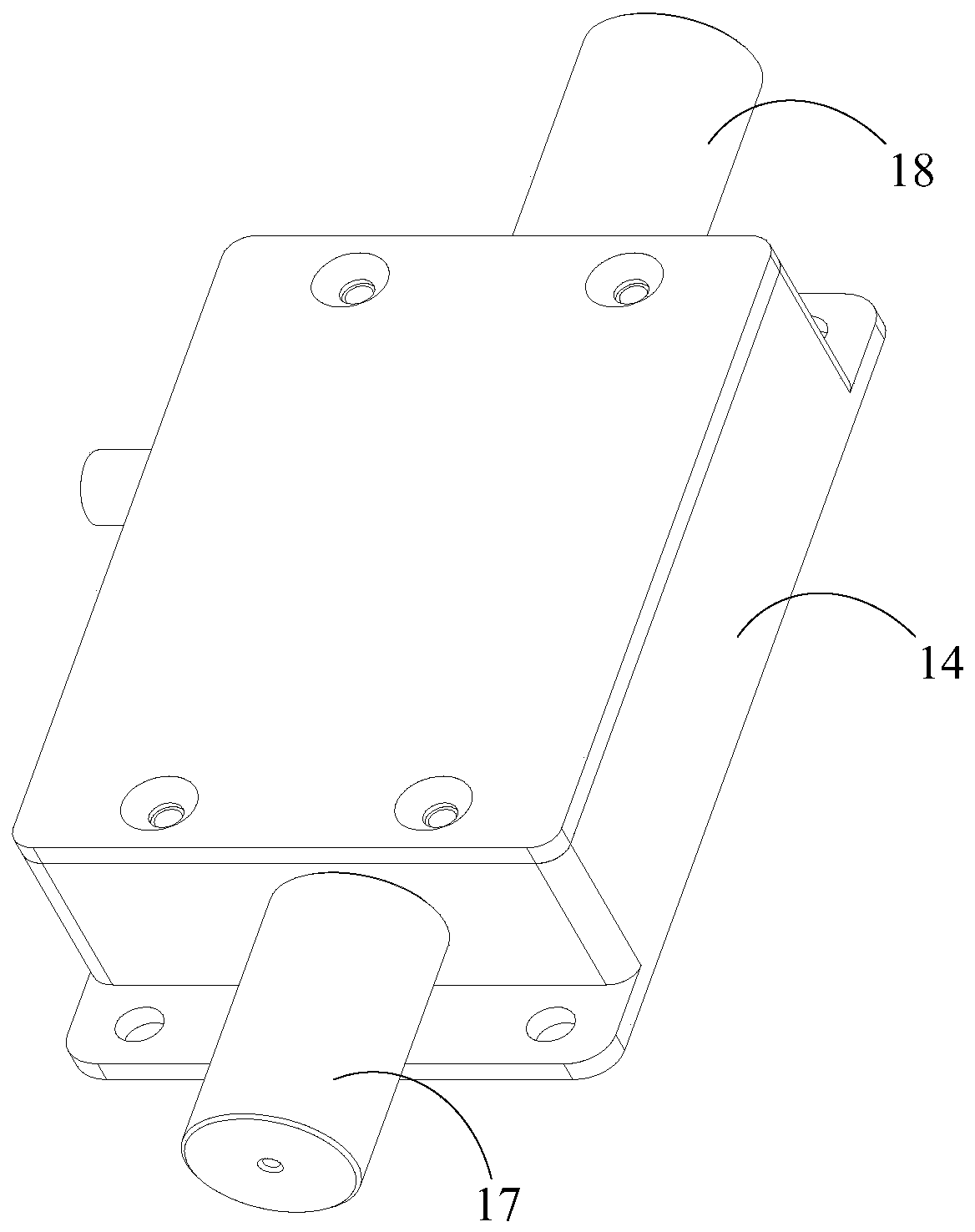
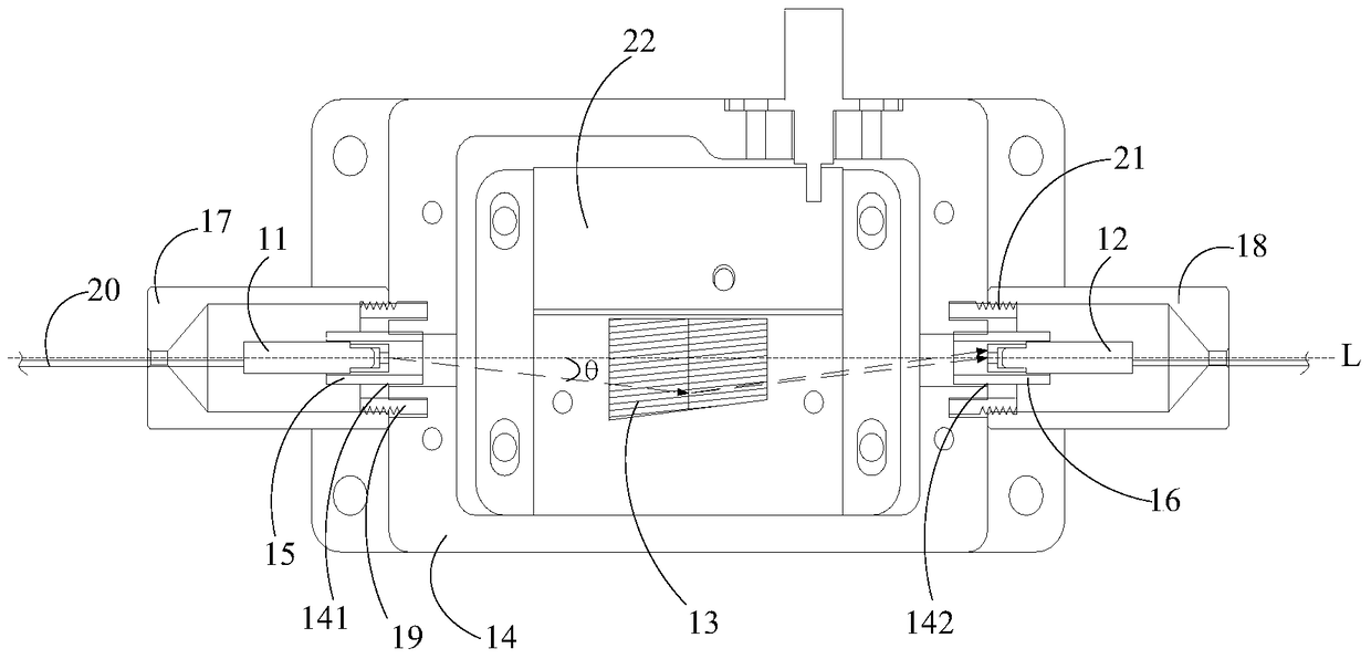
[0024] refer to Figure 1 to Figure 5 , in an embodiment of the acousto-optic Q switch of the present invention, the acousto-optic Q switch includes a first collimator 11, an acousto-optic crystal 12 and a second collimator 13 arranged in sequence along the propagation direction of the light, and the light from the first collimator The collimator 11 exits, enters the acousto-optic crystal 12, and then exits the second collimator 13.

[0025] Wherein, the first collimator 11 and the second collimator 13 are coaxially arranged, that is, the centerline of the first collimator 11 and the centerline of the second collimator are on the same straight line, as image 3 The axis L shown. Moreover, the light output angle θ of the first collimator 11 is the Bragg angle, therefore, the light 30 emitted from the first collimator 11 exits at the Bragg angle, and enters the acou...


PUM


Abstract

The invention discloses an acousto-optic Q switch and a laser device. The acousto-optic Q switch comprises a first collimator, acousto-optic crystal and a second collimator, wherein the first collimator, the acousto-optic crystal and the second collimator are sequentially arranged along the propagation direction of light; the first collimator and the second collimator are coaxially arranged; and a light outlet angle of the first collimator is a bragg angle. In the manner, the dimming frequency of each collimator can be reduced; and the dimming of each collimator is relatively simple and convenient.

Description

technical field [0001] The invention relates to the field of laser technology, in particular to an acousto-optic Q switch and a laser device. Background technique [0002] Laser pulses with large energy and high peak power can be generated by using Q-switching technology. The principle of the Q-switching switch of the laser is that when the Q-switching switch is turned off, the laser resonator is in a state of low Q value, the loss is large, the oscillation threshold is high, and the laser oscillation cannot be formed in the resonator. Under the action of the pump source, the laser medium When the number of upper-level inversion particles accumulates in a large amount, when the accumulation reaches the maximum value (saturation value), the Q-switching switch is quickly turned on, the laser resonator is in a high-Q state, the loss is greatly reduced, the oscillation threshold is suddenly reduced, and the laser oscillation is rapidly established. In a very short period of tim...

Claims


Application Information

Patent Timeline
Patent Type & Authority Patents(China)
IPC IPC(8): H01S3/117H01S3/067
Inventor 李云丰
Owner SHENZHEN SUPER LASER TECH
Learn More