Optical network central office end equipment data synchronization method and system

A central office equipment and data synchronization technology, applied in the field of communication, can solve the problems of slow online of optical network unit equipment, slow transmission of configuration information, slow transmission of configuration files, etc., to solve the slow configuration process, solve the slow transmission, and speed up the online speed Effect

Active Publication Date: 2015-11-11
湖州帷幄知识产权运营有限公司
View PDF4 Cites 2 Cited by
  • Summary
  • Abstract
  • Description
  • Claims
  • Application Information

AI Technical Summary

Problems solved by technology

[0002] The optical network central office equipment is a terminal equipment used to connect the optical fiber trunk line. In the traditional optical network central office equipment, there are generally multiple optical network port modules, and the synchronous serial connection mode is adopted. When the optical network port module starts Finally, the optical network port module sends the startup message to the optical network central office device, and the optical network central office device sends the configuration information belonging to the optical network port module to the optical network port module. The problem brought by this method is that the configuration information is transmitted Very slow, thus causing the ONU device connected to the optical network port module to go online slowly
[0003] Some improved methods use the optical network port module to send multiple messages of the same type to the optical network central office equipment each time. Although the transmission speed can be accelerated to a certain extent, the serial method cannot fundamentally solve the configuration problem. Slow file transfer issues

Method used


Image

  • Optical network central office end equipment data synchronization method and system
  • Optical network central office end equipment data synchronization method and system
  • Optical network central office end equipment data synchronization method and system

Examples


Embodiment Construction

[0034] The present invention will be further described below in conjunction with the accompanying drawings and specific embodiments, but not as a limitation of the present invention.

[0035] The technical scheme of the invention includes a method for synchronizing data of an optical network central office device.

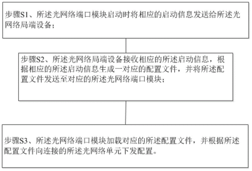
[0036] Such as figure 1 As shown, an embodiment of a data synchronization method for optical network central office equipment, the optical network central office equipment is connected to a plurality of optical network port modules, and each optical network port module is connected to a plurality of optical network units, which specifically includes the following steps:

[0037] Step S1, when the optical network port module is started, the corresponding start information is sent to the optical network central office device;

[0038] Step S2, the optical network central office device receives the corresponding startup information, generates a corresponding configur...


PUM


Abstract

The invention provides an optical network central office end equipment data synchronization method and a system. Optical network central office end equipment is connected to multiple optical network port modules. Each optical network port module is connected with multiple optical network units. The method is characterized by comprising the following steps of S1, sending corresponding start information to the optical network central office end equipment when the optical network port modules are started; S2, the optical network central office end equipment receiving the corresponding start information, generating corresponding configuration files according to the corresponding start information, and sending the configuration files to the corresponding optical network port modules; and S3, the optical network port modules loading the corresponding configuration files, and sending configuration to the connected optical network units according to the configuration files. The invention solves problems that the optical network central office end equipment sends the configuration files to the optical network port modules slowly, and the configuration process of the optical network port modules is slow.

Description

technical field [0001] The invention relates to the communication field, in particular to a data synchronization method and system for an optical network central office device. Background technique [0002] The optical network central office equipment is a terminal equipment used to connect the optical fiber trunk line. In the traditional optical network central office equipment, there are generally multiple optical network port modules, and the synchronous serial connection mode is adopted. When the optical network port module starts Finally, the optical network port module sends the startup message to the optical network central office device, and the optical network central office device sends the configuration information belonging to the optical network port module to the optical network port module. The problem brought by this method is that the configuration information is transmitted It is very slow, which causes the ONU device connected to the optical network port m...

Claims


Application Information

Patent Timeline
Patent Type & Authority Applications(China)
IPC IPC(8): H04L7/00
Inventor 韩永华
Owner 湖州帷幄知识产权运营有限公司
Why Eureka
Try Eureka