Synchronous carbon and nitrogen removing reactor

A reactor and carbon removal technology, applied in the field of biological treatment of high-concentration ammonia nitrogen wastewater, can solve the problems of increased power consumption and operating costs, increased investment and operating costs, slow proliferation of nitrifying bacteria, etc., to reduce infrastructure investment and operation cost, save the sludge return link, and simplify the effect of mixed liquid return

Active Publication Date: 2015-11-18
JIANGSU ZHAOSHENG ENVIRONMENTAL PROTECTION TECH CO LTD
View PDF4 Cites 3 Cited by
  • Summary
  • Abstract
  • Description
  • Claims
  • Application Information

AI Technical Summary

Problems solved by technology

[0003] Traditional biological denitrification technology is currently the most widely used denitrification technology, but there are many problems in the traditional biological denitrification process: (1) The process is long, the area is large, and the infrastructure investment is high
(2) Due to the slow proliferation of nitrifying bacteria and the difficulty in maintaining a high biological concentration, especially in low-temperature winters, the HRT of the system is longer, requiring a larger aeration tank, which increases investment and operating costs
(3) In order to maintain a high biological concentration and obtain a good denitrification effect, the system must simultaneously return sludge and nitrifying liquid, which increases power consumption and operating costs
(4) The impact resistance of the system is weak, and high-concentration NH and NO wastewater will inhibit the growth of nitrifying bacteria
(5) The acidity produced in the nitrification process needs to be neutralized by adding alkali, which not only increases the treatment cost, but also may cause secondary pollution

Method used


Image

  • Synchronous carbon and nitrogen removing reactor

Examples


Embodiment Construction

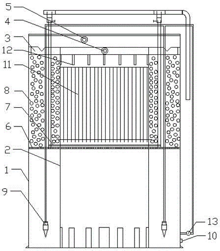
[0017] Preferred embodiments of the present invention will be described below in conjunction with the accompanying drawings.

[0018] Such as figure 1 As shown, a synchronous decarbonization and denitrification reactor according to the present invention is composed of a coaxial outer cylinder 1 and an inner cylinder 2, the top of the outer cylinder 1 is provided with a cover plate, and the upper end of the outer cylinder 1 is provided with a There is a water collection outlet weir 3 and the water collection outlet weir 3 is connected to the outlet pipe, a water outlet 4 is arranged in the middle of the upper end of the water collection outlet weir 3 and an overflow port 5 is arranged above the water outlet 4, and the outer Both the cylinder 1 and the middle of the inner cylinder 2 are provided with a perforated partition 6, and the perforated partition 6 divides the outer cylinder 1 and the inner cylinder 2 into upper and lower chambers. There is an aeration pipe 7, above whi...


PUM


Abstract

The invention discloses a synchronous carbon and nitrogen removing reactor which is suitable for the treatment of waste water with high ammonia nitrogen and low carbon and nitrogen ratio, in particular for the treatment of kitchen waste water, an anaerobic digestion solution and the like which are similar to the waste water with high ammonia nitrogen and low carbon and nitrogen ratio. The synchronous carbon and nitrogen removing reactor mainly comprises a cylindrical inner cylinder body and a cylindrical outer cylinder body which are coaxial, wherein an aeration device, a jet device, filler, an effluent weir and the like are arranged in the cylinder bodies; biological filter as a carrier is distributed in the inner cylinder; flow-separated ball filler as a carrier is put into the outer cylinder; after the anaerobic digestion solution with the high ammonia nitrogen is treated by the reactor, the removal rate of the ammonia and the nitrogen can reach 75 to 90 percent, and the removal rate of CODCr (Chemical Oxygen Demand) can reach 55 to 65 percent.

Description

technical field [0001] The invention relates to a synchronous decarbonization and denitrification reactor, which belongs to the technical field of biological treatment of high-concentration ammonia-nitrogen wastewater, and is especially suitable for the treatment of similar high-ammonia-nitrogen and low-carbon-nitrogen ratio wastewater such as digestive juice produced after anaerobic fermentation of kitchen wastewater . Background technique [0002] Nitrogen in the traditional biological denitrification process exists in the form of organic nitrogen, ammonia nitrogen, nitrite nitrogen and nitrate. Only 0% to 5%. Traditional biological denitrification technology follows the discovered nitrogen cycle mechanism in nature. Organic nitrogen undergoes ammonification, nitrosation, nitrification and denitrification under the action of ammonifying bacteria, nitrosifying bacteria, nitrifying bacteria and denitrifying bacteria in sequence. Finally, it turns into nitrogen and overflow...

Claims


Application Information

Patent Timeline
Patent Type & Authority Applications(China)
IPC IPC(8): C02F3/02
CPCY02W10/10
Inventor 尹志强尹曙辉
Owner JIANGSU ZHAOSHENG ENVIRONMENTAL PROTECTION TECH CO LTD
Why Eureka
Try Eureka