Tensioning device for applying pretensioning force to fiber cloth materials and tensioning method of tensioning device

A technology for applying pre-tensioning and tensioning devices to fabrics is applied in the processing of building materials, building maintenance, construction, etc. It can solve the problems of uneven force on fiber fabrics and difficult force measurement, and achieve good anchoring effect and simple operation. , widely used effect

Inactive Publication Date: 2015-11-18
HUNAN UNIV
View PDF12 Cites 12 Cited by
  • Summary
  • Abstract
  • Description
  • Claims
  • Application Information

AI Technical Summary

Problems solved by technology

[0008] The object of the present invention is to provide a tensioning device and a tensioning method for applying a pre-tension force to the fiber cloth, which is used to self-lock the fiber cloth with the roller and uniformly transmit force when stretching the fiber cloth. The rolling groove controls its movement in the horizontal track specified by the slideway to solve the problems of uneven force on the fiber cloth and difficulty in force measurement when the fiber cloth is stretched.

Method used


Image

  • Tensioning device for applying pretensioning force to fiber cloth materials and tensioning method of tensioning device
  • Tensioning device for applying pretensioning force to fiber cloth materials and tensioning method of tensioning device
  • Tensioning device for applying pretensioning force to fiber cloth materials and tensioning method of tensioning device

Examples


Embodiment Construction

[0036] Embodiments of the present invention will be further described below in conjunction with the accompanying drawings.

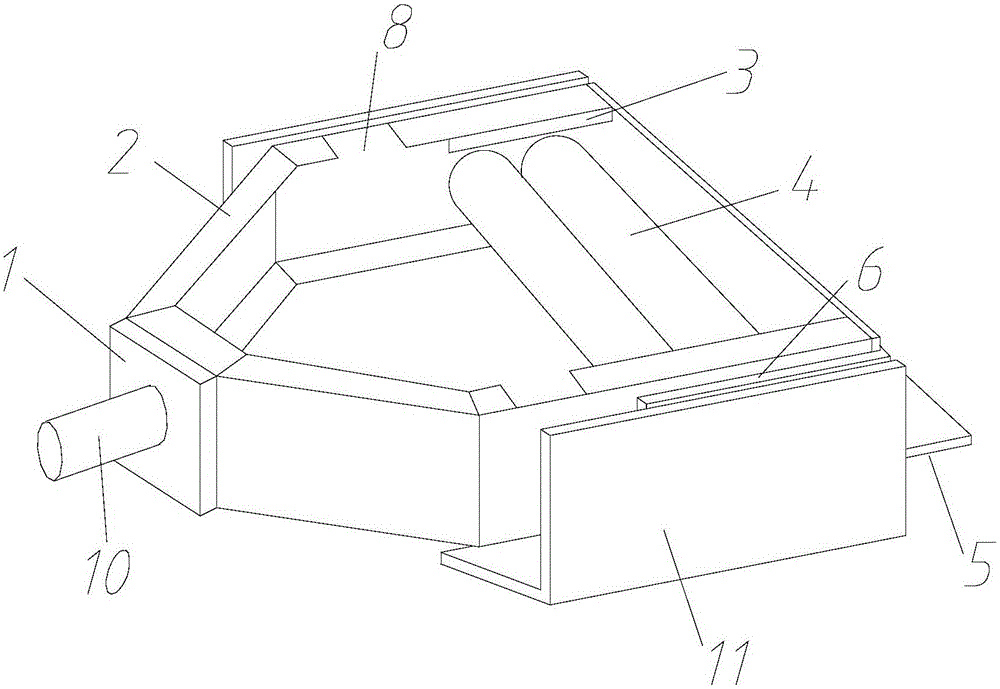
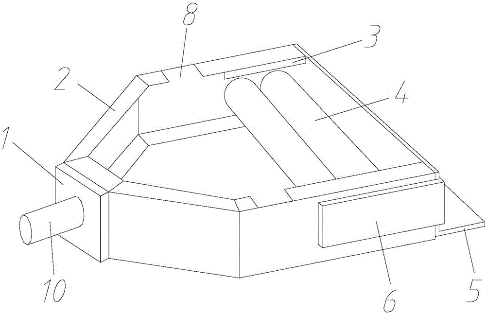
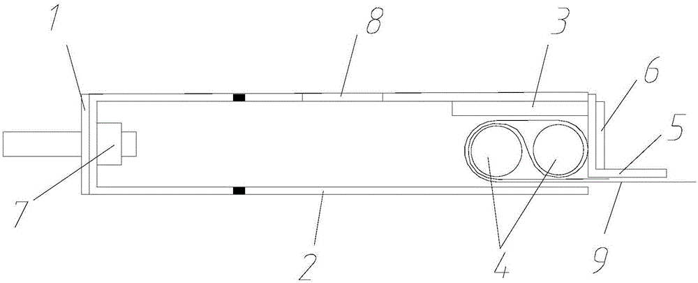
[0037] Refer to attached Figure 1-3 As shown in the figure, a tensioning device for applying pretension to the fiber cloth includes a steel baffle slideway 11 fixed at both ends, and a rolling groove 2 is arranged in the slideway 11, and can be placed in the slideway 11. 11 slide freely.

[0038] Two rollers 4 are put into the rolling groove 2 through the upper flange opening 8 of the rolling groove 2, and they can roll along the horizontal direction of the rolling groove 2, and are used for winding and self-locking fixing of the fiber cloth material 9.

[0039] An L-shaped baffle 5 is provided at the tension end of the rolling groove 2 for resisting the roller 4 .

[0040] The anchoring end of the rolling groove 2 has a trapezoidal structure, and a reinforcing steel plate 1 is provided at the end.

[0041] A backing plate 3 is also provided at the u...


PUM


Abstract

The invention discloses a tensioning device for applying a pretensioning force to fiber cloth materials and a tensioning method of the tensioning device. The tensioning device comprises a slide way (11), wherein a rolling groove (2) is arranged in the slide way (11) and can freely slide in the slide way (11); two rolling shafts (4) are arranged in the rolling groove (2), can roll along the horizontal direction of the rolling groove (2), and is used for winding the fiber cloth materials so that the fiber cloth materials are locked and fixed; an opening (8) is formed in an upper flange of the rolling groove (2); a base plate (3) is arranged at a position, which is close to the upper flange of a tensioning end, of the rolling groove (2); an L-shaped baffle (5) is arranged at the tensioning end of the rolling groove (2) and is abutted to the rolling shafts (4); and by the L-shaped baffle (5), end rigidity is improved. A fiber cloth material anchoring effect is excellent, through displacement control loading after tensioning, the outer end of a bolt bar is connected with a sensor, magnitude of a tensioning force can be measured directly, the problem that when fiber cloth materials are tensioned by another device, force is difficult to measure is solved, the fiber cloth materials are wound on the rolling shafts, and the problem that the fiber cloth materials cannot be stressed evenly is solved.

Description

technical field [0001] The invention belongs to the field of reinforcement of prestressed composite boards, in particular to a tensioning device and a tensioning method for applying pretension to fiber cloth. Background technique [0002] Fiber cloth has been used by more and more people in recent years because of its light weight, high strength, corrosion resistance, and convenient construction. It has achieved great benefits in the field of prestressed plate reinforcement and structural repair. Most of the commonly used fiber cloth reinforcement is to directly attach non-prestressed fiber cloth to the surface of the structure through adhesives. The surface of the structure is easily damaged by external conditions, easily peeled off by force, and glued to the surface. Performance is concerned, and its durability cannot be guaranteed. When the prestressed fiber cloth composite board is reinforced, the fiber cloth is in the cement matrix and is difficult to be affected by th...

Claims


Application Information

Patent Timeline
Patent Type & Authority Applications(China)
IPC IPC(8): E04G21/12E04G23/02
Inventor 周芬徐文杜运兴
Owner HUNAN UNIV
Why Eureka
Try Eureka