
A support frame for building construction

A technology of building construction and support frame, which is applied in construction, building structure, and on-site preparation of building components, etc. Height adjustable, increased shock absorption, high support strength

Inactive Publication Date: 2017-03-22
ZHENGZHOU TECHN COLLEGE +6
View PDF9 Cites 1 Cited by
  • Summary
  • Abstract
  • Description
  • Claims
  • Application Information

AI Technical Summary

Problems solved by technology

The supporting force on the building is basically large, so the single support rod is easy to bend when used, the service life of the support is short, and once the top of the support is tilted, the lifted building will be unevenly stressed and easy to tilt or deviate, or the support If the support fails and damages the upper part of the building, it will seriously affect the quality of the building, and even cause the building to collapse and cause danger
At the same time, when the bracket is fine-tuned, the uneven force on the fine-tuning parts or excessive pressure may cause the bracket parts to be easily damaged, or the uneven force on the bracket will cause the top bracket surface to tilt, which will also affect the quality and construction of the building. security
And when the existing support is installed, the rotation of the support rod or the upper support plate will affect the effect of the support, and may even cause problems with the construction quality of the building. Some brackets can only be rotated as a whole or disassembled and then reinstalled. The supported objects may still not be adjusted to the correct angle. The adjustment is very troublesome and laborious, and the adjustment is not accurate and needs repeated operations.

Method used


Image

  • A support frame for building construction
  • A support frame for building construction

Examples


Embodiment Construction

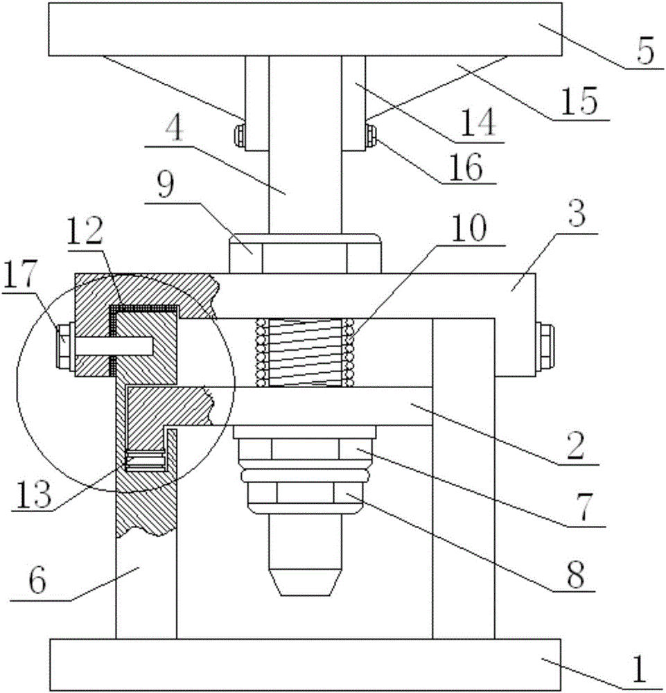
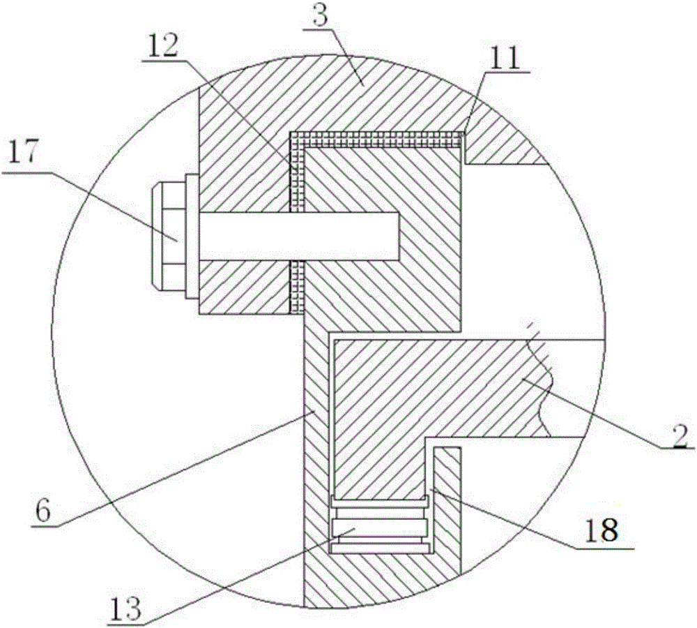
[0014] see figure 1 and figure 2 The shown support frame for building construction includes a base 1, a fixing plate 2, a positioning plate 3, a supporting screw 4 and a supporting plate 5, and two supporting columns 6 are symmetrically arranged on the base 1, and the positioning The plate 3 is arranged on the upper part of the two supporting columns 6, the fixing plate 2 is arranged between the two supporting columns 6 at the lower part 3 of the positioning plate, the supporting screw 4 is arranged through the positioning plate 3 and the fixing plate 2, and the upper end extends To the upper part of the positioning plate 3, the lower end extends to the lower part of the fixing plate 2, the support plate 5 is mounted on the support screw 4 extending to the upper part of the positioning plate 3, and the support screw 4 at the lower part of the fixing plate 2 is provided with a first tightening plate. The fixing nut 7 is provided with a pre-tightening nut 8 on the support scre...


PUM


Abstract

The invention discloses a support frame for building construction. The support frame comprises a base, a fixing plate, a positioning plate, a support screw rod and a support plate, wherein two support posts are symmetrically arranged on the base; the positioning plate is arranged at the upper parts of the two support posts; the fixing plate is arranged between the two support posts arranged at the lower part of the positioning plate; the support screw rod is arranged in a way of penetrating through the positioning plate and the fixing plate; the upper end of the support screw rod extends to the upper part of the positioning plate; the lower end of the support screw rod extends to the lower part of the fixing plate; the support plate is arranged on the support screw rod extending to the upper part of the positioning plate; a first fastening screw nut is arranged on the support screw rod arranged at the lower part of the fixing plate; a pre-tightening screw nut is arranged on the support screw rod arranged at the lower part of the first fastening screw nut; a second fastening screw nut is arranged on the support screw rod arranged at the upper part of the positioning plate; and a damping spring is arranged on the support screw rod arranged between the positioning plate and the fixing plate. The support frame for building construction has the advantages that the structure is simple; the use and the installation are convenient; the operation is simple; the safety is high; the support strength is high; the support height is adjustable; the cost is low; the damping effect is good; the service life is long; and the safe and reliable effects are achieved.

Description

technical field [0001] The invention relates to a support frame for building construction. Background technique [0002] Most of the existing building supports are supported by a single support rod, and the fine-tuning components are used for final lifting. The support force on the building is basically large, so the single support rod is easy to bend when used, the service life of the bracket is short, and once the top of the bracket is inclined, the jacked building will be unevenly stressed and easy to tilt or deviate, or the bracket If the support fails and damages the upper building, it will seriously affect the quality of the building, and even the collapse of the building will bring danger. At the same time, when the bracket is fine-tuned, the bracket components may be easily damaged due to the uneven force of the fine-tuning components or the excessive force and pressure, or the uneven force of the bracket may cause the top bracket surface to tilt, which will also af...

Claims


Application Information

Patent Timeline
Patent Type & Authority Patents(China)
IPC IPC(8): E04G25/06
Inventor 张丹丹曹秀丽马李亚赵全成程东谊王晨阳王晓委
Owner ZHENGZHOU TECHN COLLEGE
Learn More