Supercharger oil seal structure

A supercharger and oil seal technology, which is applied to the sealing of engines, machines/engines, engine components, etc., can solve problems such as leakage, leakage, and lubricating oil leakage, and achieve improved oil sealing capabilities, low manufacturing costs, and reliable performance Effect

Active Publication Date: 2017-08-22
WUXI CUMMINS TURBO TECH
View PDF1 Cites 0 Cited by
  • Summary
  • Abstract
  • Description
  • Claims
  • Application Information

AI Technical Summary

Problems solved by technology

However, when the rotating shaft rotates at high speed, because the oil throwing cylindrical surface on the shaft seal body is very short, only part of the lubricating oil can be thrown out to reach the cavity of the shaft seal sleeve, and a large amount of lubricating oil is accumulated on the shaft seal body. Once the liquid level is higher than the shoulder height of the shaft seal body, it will diffuse into the gap between the shaft seal body and the shaft seal sleeve, and then leak to the compressor end
The small-sized oil throwing groove added on the shaft seal body can only take away a small part of the oil passing through the gap between the shaft seal sleeve and the shaft seal body, so a large amount of lubricating oil still leaks to the compressor end

Method used


Image

  • Supercharger oil seal structure
  • Supercharger oil seal structure
  • Supercharger oil seal structure

Examples


Embodiment Construction

[0023] The specific embodiments of the present invention will be further described below in conjunction with the accompanying drawings.

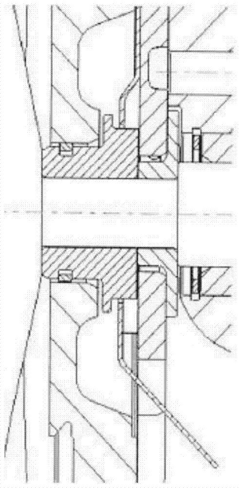
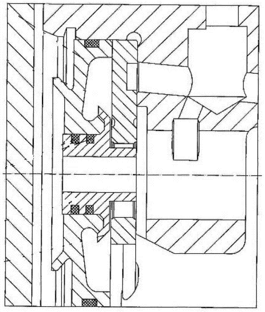
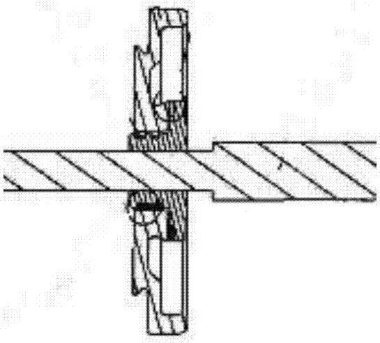
[0024] Figure 1~7 , including compressor housing 1, impeller 2, shaft seal 3, first inner peripheral surface 3-1, second inner peripheral surface 3-2, groove 3-3, support part 3-4, thrust bearing 4. Middle casing 5, oil passage 5-1, middle casing cavity 5-2, rotating shaft 6, volute casing 7, fixed sleeve 8, shaft seal body 9, sealing ring groove 9-1, first ring protrusion 9- 2. The second ring protrusion 9-3, the lock nut 10, the sealing ring 11, etc.

[0025] Such as Figure 6 As shown, the present invention is a supercharger oil seal structure, including a shaft seal body 9, a shaft seal sleeve 3 and a seal ring 11, the shaft seal body 9 is fixed on the turbine shaft 6, and the circumferential surface of the shaft seal body 9 is sequentially A seal ring groove 9-1, a first ring protrusion 9-2, and a second ring protrusion 9-3 are prov...


PUM


Abstract

The invention relates to the technical field of superchargers, in particular to a supercharger oil seal structure, including a shaft seal body, a shaft seal sleeve and a seal ring, the shaft seal body is fixed on the turbine rotating shaft, and the circumferential surface of the shaft seal body A seal ring groove, a first circular ring protrusion, and a second circular ring protrusion are provided in sequence, the seal ring is mounted on the seal ring groove, the shaft seal sleeve is mated and connected to the shaft seal body, and the first inner peripheral surface of the shaft seal sleeve Pressed on the sealing ring, the second inner peripheral surface of the shaft seal sleeve is placed outside the protrusion of the first ring. The invention has the advantages of simple structure, reliable performance and low manufacturing cost. It can effectively shake off the lubricating oil from the rotating parts and make it flow back into the oil chamber smoothly. ability to meet customer needs.

Description

technical field [0001] The invention relates to the technical field of superchargers, in particular to a supercharger oil seal structure. Background technique [0002] In turbocharger applications, the power is transmitted from the vortex end to the compressor end by the high-speed rotating shaft, and the intermediate casing is used to connect the volute end and the compressor end housing, while supporting the high-speed rotating shaft. When the supercharger is working, sufficient oil lubrication and cooling is required between the middle shell and the shaft; the shaft seal sleeve, the shaft seal body and the seal ring form the oil seal structure at the compressor end, which makes the lubrication through the mechanical seal and the oil throwing function After the oil has functioned, it can return to the middle casing oil cavity, preventing a large amount of lubricating oil from leaking to the compressor end. Since the seal ring between the shaft seal sleeve and the shaft se...

Claims


Application Information

Patent Timeline
Patent Type & Authority Patents(China)
IPC IPC(8): F16J15/16F01D25/18
CPCF01D25/18F16J15/16
Inventor 朱薇
Owner WUXI CUMMINS TURBO TECH
Why Eureka
Try Eureka