Method for restraining torque ripple of surface-mounted permanent magnet synchronous motor by use of current harmonic waves
A permanent magnet synchronous motor, current harmonic technology, applied in torque ripple control and other directions, can solve the problems of inaccurate current zero-crossing detection, complex algorithm, wrong compensation and so on
- Summary
- Abstract
- Description
- Claims
- Application Information
AI Technical Summary
Problems solved by technology
Method used
Image
Examples
Embodiment 1
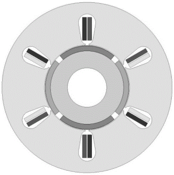
[0111] 101: figure 2 It is a finite element model of a 4-pole 6-slot double-winding surface-mounted permanent magnet synchronous motor. The rated frequency of the motor is 50Hz, the rated speed is 1500r / min, and the effective value of the rated current is 3A, that is, I 1 =4.24A. Surface-mounted permanent magnet synchronous motors usually use i d =0 control mode to control, that is, ψ 1 =0.
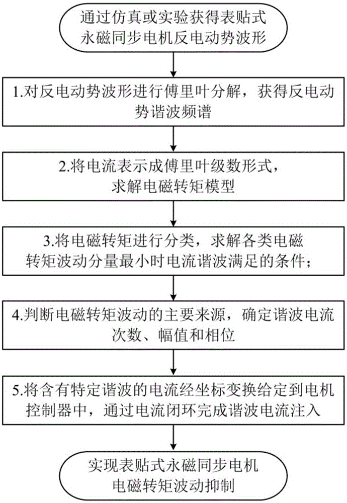
[0112] 102: The three opposite electromotive force waveforms of the motor can be obtained through finite element simulation, such as image 3 (a). The spectral distribution of each harmonic of the back EMF and the amplitude of each harmonic are further obtained through Fourier transform, such as image 3 (b).
[0113] 103: By image 3 (b) It can be seen that the 5th and 7th harmonics in the back EMF waveform are the main harmonics, and the amplitudes of other harmonics are all less than 2% of the fundamental amplitude, so other harmonics can be ignored, focusing on the 5th and 7t...
Embodiment 2
[0122] 101: Figure 5 It is a finite element model of a 4-pole 12-slot single-layer winding surface-mounted permanent magnet synchronous motor. The rated frequency of the motor is 50Hz, the rated speed is 1500r / min, and the effective value of the rated current is 3A, that is, I 1 =4.24A. Surface-mounted permanent magnet synchronous motors usually use i d =0 control mode to control, that is, ψ 1 =0.
[0123] 102: The three opposite electromotive force waveforms of the motor can be obtained through finite element simulation, such as Image 6 (a). The spectral distribution of each harmonic of the back EMF and the amplitude of each harmonic are further obtained through Fourier transform, such as Image 6 (b).
[0124] 103: By Image 6 (b) It can be seen that the 5th and 7th harmonics in the back EMF waveform are the main harmonics, and the amplitudes of other harmonics are all less than 2% of the fundamental amplitude, so other harmonics can be ignored, focusing on the 5th...
PUM
 Abstract
Description
Claims
Application Information
 - R&D
- Intellectual Property
- Life Sciences
- Materials
- Tech Scout
- Unparalleled Data Quality
- Higher Quality Content
- 60% Fewer Hallucinations
Browse by: Latest US Patents, China's latest patents, Technical Efficacy Thesaurus, Application Domain, Technology Topic, Popular Technical Reports.
© 2025 PatSnap. All rights reserved.Legal|Privacy policy|Modern Slavery Act Transparency Statement|Sitemap|About US| Contact US: help@patsnap.com


