
pneumatic tire

A technology for pneumatic tires and beads, which is applied to the reinforcement layer of pneumatic tires, motorcycle tires, tire parts, etc., can solve the problems of reduced rigidity, reduced tire rigidity, reduced handling stability, etc. Improved handling stability and excellent handling stability

Active Publication Date: 2018-12-18
SUMITOMO RUBBER IND LTD
View PDF10 Cites 0 Cited by
  • Summary
  • Abstract
  • Description
  • Claims
  • Application Information

AI Technical Summary

Problems solved by technology

However, since the height of the bead core is limited, the rigidity of the tire decreases
This reduction in rigidity reduces handling stability

Method used


Image

  • pneumatic tire
  • pneumatic tire
  • pneumatic tire

Examples


Embodiment 1

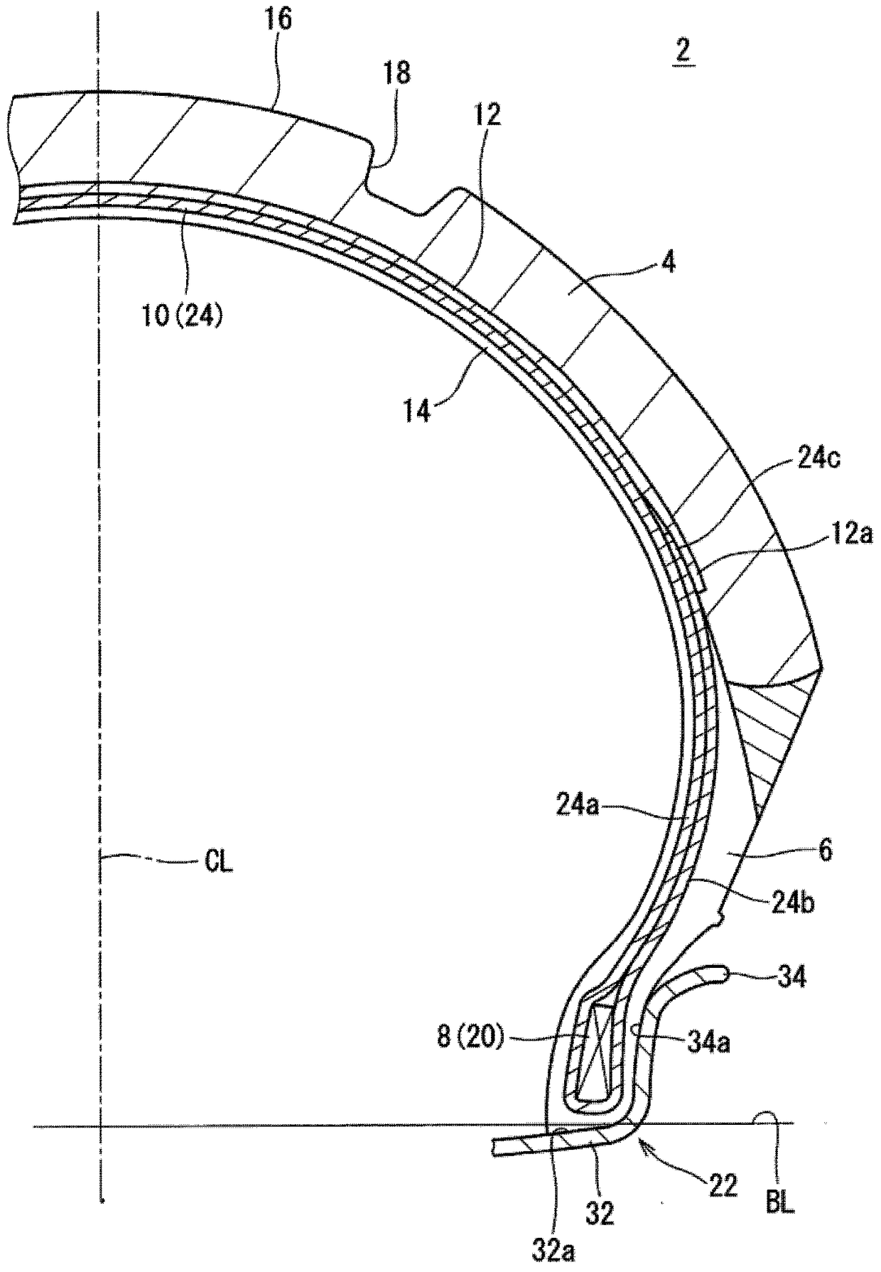
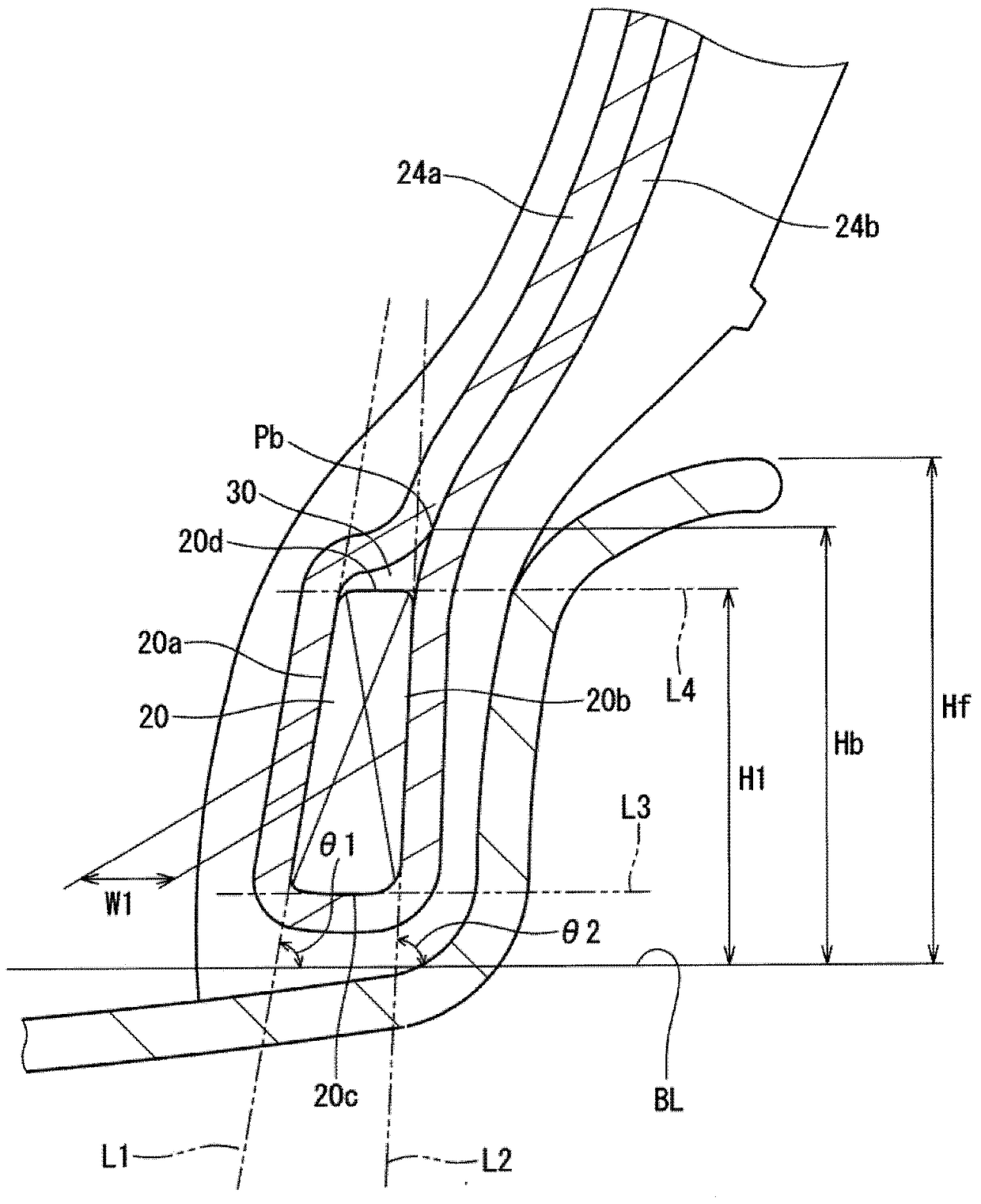
[0058] obtain figure 1 The structure of the tire shown. Table 1 shows the lap width W2, bead core height H1, inclination angles θ1 and θ2 of this tire. The tire size is "180 / 55ZR17".

Embodiment 2-3

[0062] The inclination angles θ1 and θ2 are as shown in Table 1, and a tire was obtained in the same manner as in Example 1 with other configurations.

Embodiment 4 and Embodiment 6

[0064] The overlapping width W2, the inclination angles θ1 and θ2 are shown in Table 1 and Table 2. A tire was obtained in the same manner as in Example 1 with other structures.


PUM


Abstract

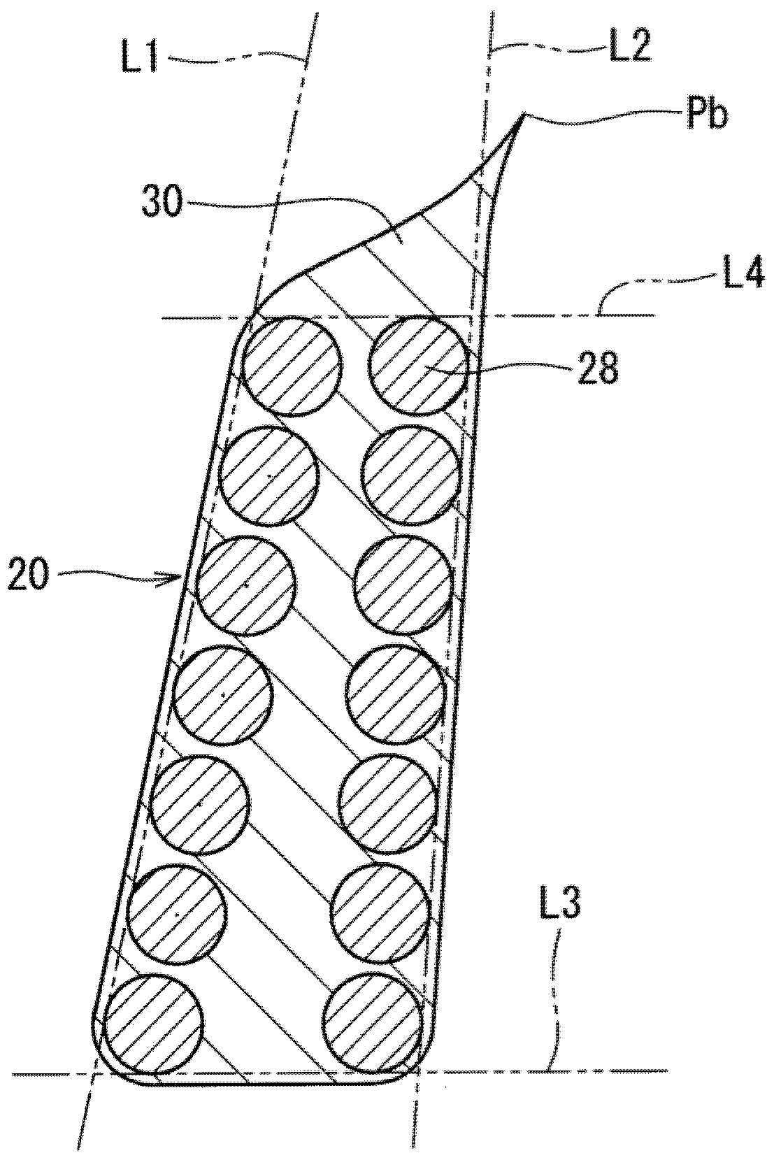
The present invention provides a pneumatic tire excellent in both steering stability and riding comfort. The carcass ply (24) of the tire (2) is provided with a main part (24a) and a turn-back part (24b). The main part (24a) is bridged between the bead (8) on one side and the bead (8) on the other side. 8), the folded portion (24b) extends from the axial outside of the bead (8) toward the radial outside. The bead (8) includes a bead core (20) including bead wires extending in the circumferential direction. The number of strands of the bead core (20) is 2 or more. The number of turns of the bead core (20) is more than three times the number of strands. When the tire (2) is mounted on a regular rim (22), the radial outer end of the bead wire is located radially inward of the radial outer end of the flange (34) of the rim (22). The outer end portion (24c) of the folded portion (24b) overlaps the end portion (12a) of the belt layer (12).

Description

technical field [0001] The present invention relates to pneumatic tires. Background technique [0002] JP 2001-97010 A proposes a tire in which bead cores are increased in the radial direction. This bead core contributes to increasing the rigidity of the tire. Steering stability is improved by increasing the rigidity described above. However, the aforementioned increase in rigidity degrades ride comfort. [0003] JP 2010-137637 A proposes a tire in which the radial height of the bead core is lower than the height of the rim flange. Riding comfort is improved by limiting the height of the bead core. However, since the height of the bead core is limited, the rigidity of the tire decreases. This decrease in rigidity degrades steering stability. [0004] Patent Document 1: Japanese Patent Application Laid-Open No. 2001-97010 [0005] Patent Document 2: Japanese Unexamined Patent Application Publication No. 2010-137637 [0006] Thus, it is not easy to improve both ride co...

Claims


Application Information

Patent Timeline
Patent Type & Authority Patents(China)
IPC IPC(8): B60C15/04B60C9/02
CPCB60C2200/10B60C15/0045B60C15/04B60C2015/048Y10T152/10819B60C15/024B60C2015/009
Inventor 井坂航
Owner SUMITOMO RUBBER IND LTD
Learn More