
Pneumatic tire

a pneumatic tire and rubber technology, applied in special tyres, non-skid devices, transportation and packaging, etc., can solve the problems of reducing the stiffness of rubber, reducing the kinematic performance (e.g. handling stability), etc., to improve the tensile strength, improve the handling stability, and improve the effect of tensile strength

Inactive Publication Date: 2013-12-05
SUMITOMO RUBBER IND LTD
View PDF8 Cites 25 Cited by
  • Summary
  • Abstract
  • Description
  • Claims
  • Application Information

AI Technical Summary

Benefits of technology

The present invention is a type of tire with good handling stability, fuel economy, and tensile strength. It includes a rubber layer with carbon black, silica, and staple fibers. The staple fibers have a specific orientation angle and make up a portion of the rubber layer. This results in improved performance of the tire.

Problems solved by technology

However, when the amount of filler is reduced or filler is highly dispersed, the stiffness of rubber is likely to be reduced, which leads to the problem of decrease in kinematic performance (e.g. handling stability) of tires.

Method used


Image

  • Pneumatic tire
  • Pneumatic tire
  • Pneumatic tire

Examples


production example 1

Synthesis of Styrene-Butadiene Copolymers (1) to (5)

[0171]After the air in a 3-L autoclave equipped with a stirrer was fully replaced with nitrogen, the autoclave was charged with n-hexane, 1,3-butadiene, styrene, and tetramethylethylenediamine in amounts shown in Table 1, and the temperature in the autoclave was set to 25° C. To the mixture was added a 1.6 M solution of n-butyllithium in hexane, and the resulting mixture was polymerized at an elevated temperature (30° C.) for 60 minutes. After the conversion ratio of monomers was confirmed to be 99%, 1.5 g of 2,6-di-t-butyl-p-cresol was added as an antioxidant. In this way, styrene-butadiene copolymers (1) to (5) were obtained.

Production Example 2

Synthesis of Modified Styrene-Butadiene Copolymers (1) to (5)

[0172]A flask was charged with each of the styrene-butadiene copolymers (1) to (5), n-hexane, and AIBN in amounts shown in Table 2, and the temperature in the flask was set to 60° C. Next, after addition of a modifier to the ...

production example 2

[0194]The materials in amounts shown in Table 3, other than the sulfur and vulcanization accelerators, were mixed and kneaded using a 1.7 L Banbury mixer at 150° C. for three minutes, so that a kneaded mixture was obtained. Thereafter, the sulfur and the vulcanization accelerators were added to the kneaded mixture, and they were kneaded at 80° C. for five minutes by an open roll mill, whereby an unvulcanized rubber composition was obtained. A rubber sheet with a rubber thickness of 1.5 mm was prepared from the unvulcanized rubber composition obtained using the open roll mill. The rubber sheet was cut at predetermined angles relative to the rolling direction to prepare different rubber sheets (unvulcanized rubber layers) with differently oriented staple fibers.

[0195]Next, the obtained rubber sheets (unvulcanized rubber layers) were molded into the shape of a tread and assembled with other tire components to form an unvulcanized tire. The unvulcanized tire was press-vulcanized at 170°...


PUM

PropertyMeasurementUnit
lengthaaaaaaaaaa
widthaaaaaaaaaa
average orientation angleaaaaaaaaaa

Abstract

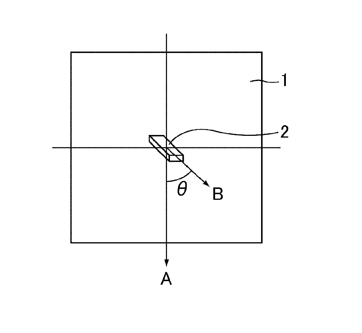
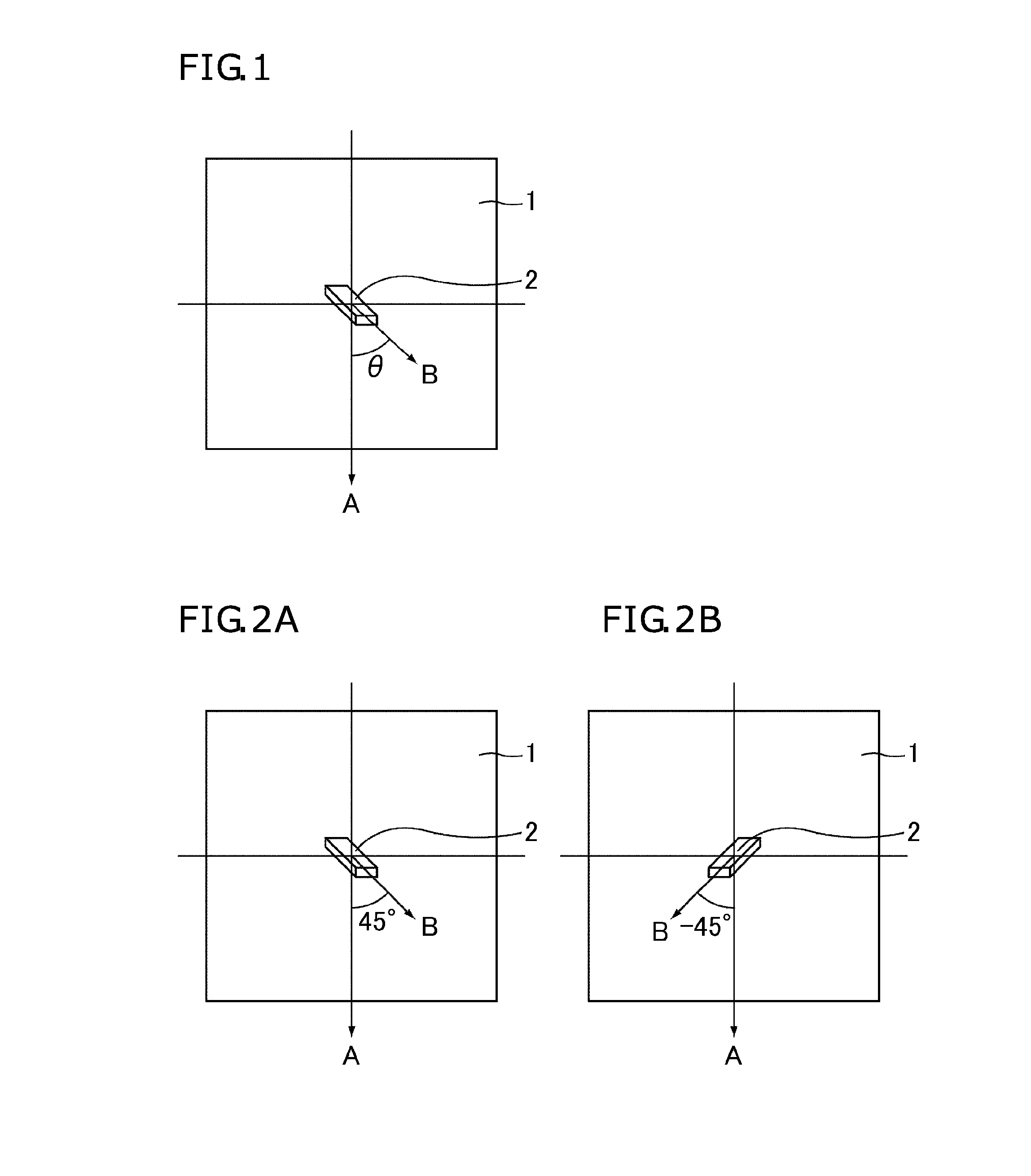
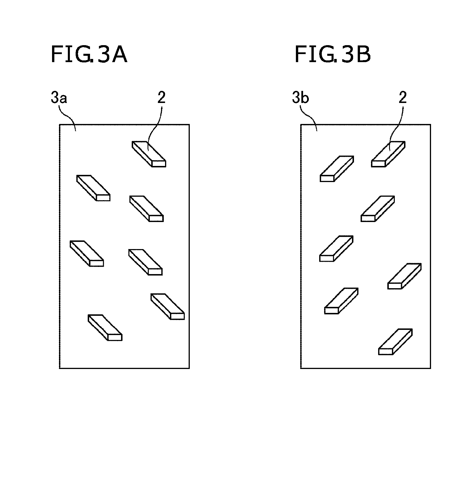
The present invention provides a pneumatic tire that has improved handling stability while maintaining good fuel economy and tensile strength or even improving these properties. The pneumatic tire includes a tread including a rubber layer formed from a rubber composition that includes: carbon black; silica; and staple fibers with an average width of 3 nm to 50 μm and an average length of 50 nm to 500 μm, the staple fibers in the rubber layer having an average orientation angle between the longitudinal direction of each staple fiber and the circumferential direction of the tire of 15° to 75°, and the staple fibers in the rubber layer including 35 to 100% of staple fibers each having an orientation angle between its longitudinal direction and the circumferential direction of the tire of 15° to 75°.

Description

TECHNICAL FIELD[0001]The present invention relates to a pneumatic tire.BACKGROUND ART[0002]For resource saving, energy saving, and environmental protection, social needs for reduction in carbon dioxide gas emission have recently been increasing. In the automotive field, in order to reduce carbon dioxide gas emission, various measures including weight saving of cars and use of electric energy have been considered.[0003]Every type of car is required to have better fuel economy by improving the rolling resistance of tires, and is also increasingly desired to have enhanced safety during running and enhanced durability. Since these properties greatly depend on the performance of tires, tires for cars are increasingly desired to have improved fuel economy, wet grip performance, handing stability, and durability (e.g. tensile strength). The performance of tires depends on various factors including the structure and materials of tires, particularly the performance of the rubber composition ...

Claims


Application Information

Patent Timeline
Patent Type & Authority Applications(United States)
IPC IPC(8): C08K7/10C08K3/36C08K3/04
CPCC08K7/10C08K3/04C08K3/36B60C1/0016B60C2011/145C08L9/00C08L9/06C08L15/00
Inventor SATO, DAISUKE
Owner SUMITOMO RUBBER IND LTD
Learn More