An all-wheel steering electrically powered unmanned vehicle chassis that is independently driven
An independently driven, unmanned vehicle technology, applied in the direction of electric steering mechanism, power steering mechanism, steering mechanism, etc., can solve problems such as difficulty in adapting, and achieve the effect of improving mobility, high motor life, and good ride comfort
- Summary
- Abstract
- Description
- Claims
- Application Information
AI Technical Summary
Problems solved by technology
Method used
Image
Examples
Embodiment 1
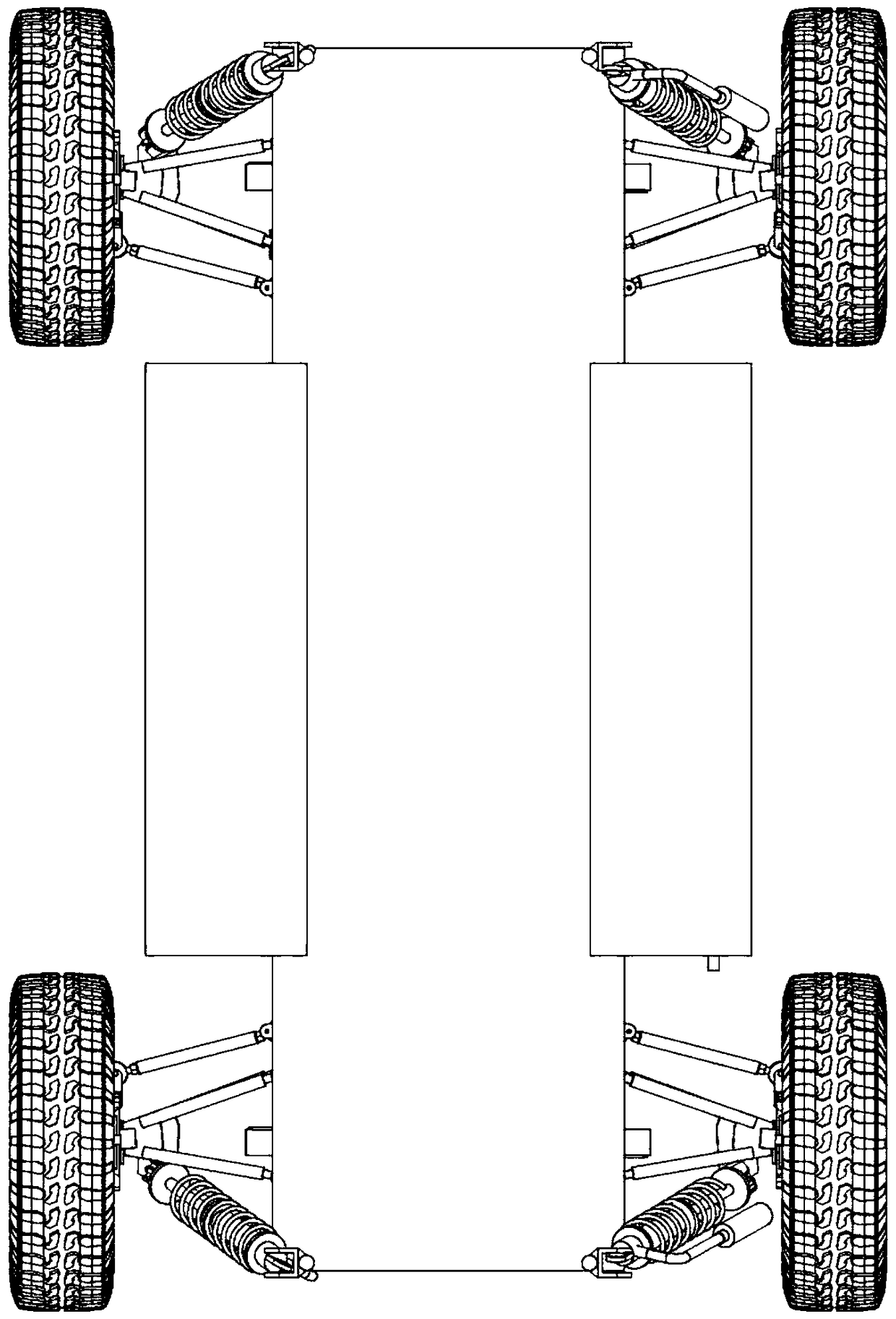
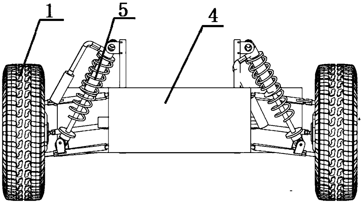
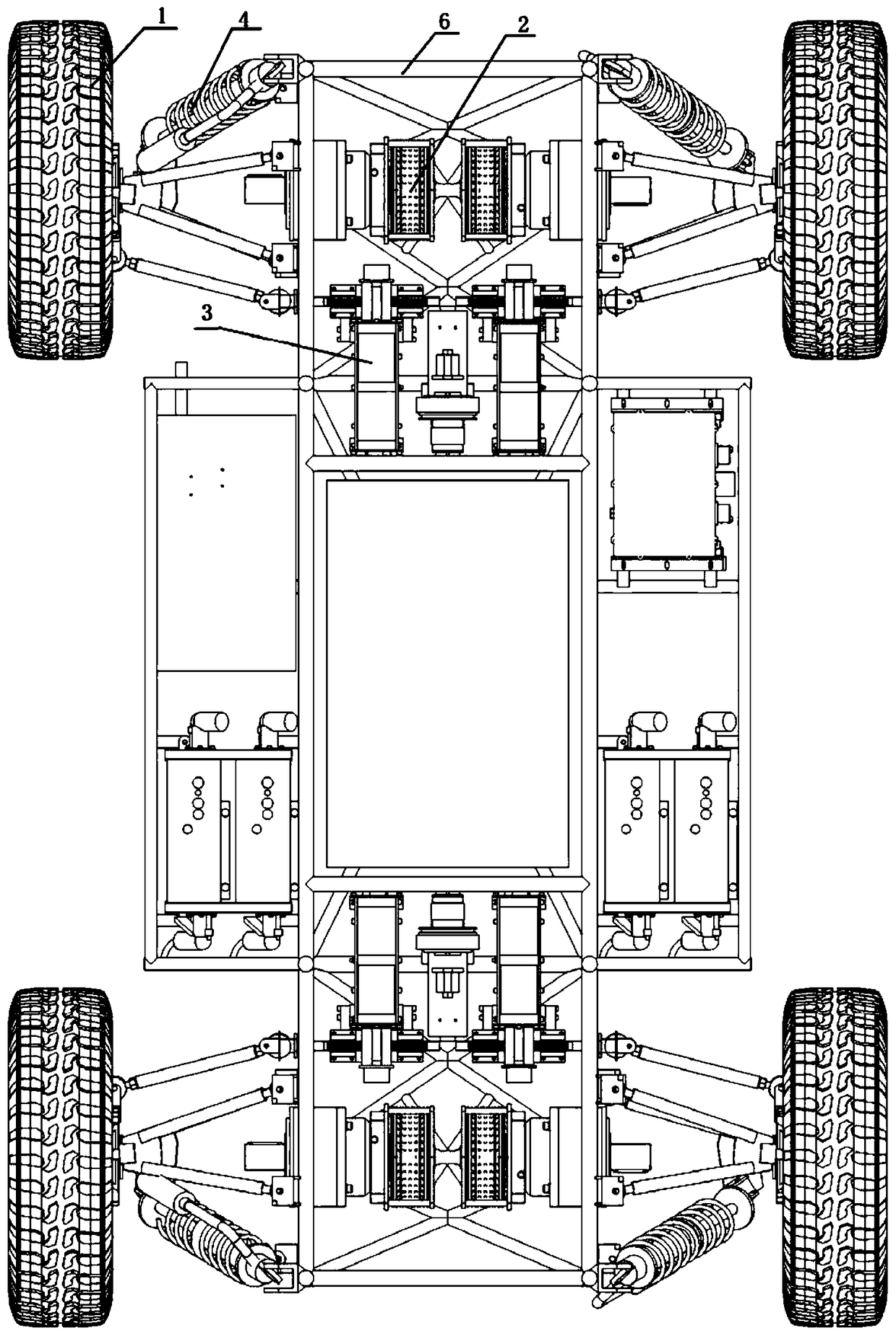
[0031] This embodiment provides an independently driven all-wheel steering electric unmanned vehicle chassis, such as Figure 1-3 As shown, the unmanned vehicle chassis includes: a body frame system, a circuit system, four wheels 1, each wheel 1 corresponds to a set of independent drive system 2, independent steering system 3, independent suspension system 4 and independent Brake system.
[0032] Here, the wheel 1 is the wheel assembly, which includes a tire 12, a rim 11, a wheel hub 10, and a steering column 9.
[0033] The body frame system includes a frame 6 and a non-load-bearing body 5. The circuit system and four drive systems, four steering systems and four braking systems are fixedly installed on the frame 6, and each wheel 1 passes through a set of suspension The system is connected to the frame 6.
[0034] Such as Figure 7 As shown, the drive system adopts a wheel-side motor independent drive system, including: a drive motor 22, a reducer 25, and a universal transmission...
Embodiment 2
[0044] The difference from Embodiment 1 above is that in order to save wheel space and facilitate the design and shape of the car body, a reversing block is added to the traditional double wishbone suspension system, specifically: the suspension system in this embodiment Includes: two cross arms, shock absorber, push rod and reversing block. The reversing block has a triangular structure, and each of its three vertices is provided with a connection point (respectively called connection point A, connection point B and connection point C); both ends of the cross arm are equipped with rod end bearings, and two cross arms One end of the cross arm is connected to the steering column by bolts, and the other end of one of the cross arms is pin-connected to the connection point C on the reversing block, the reversing block can rotate around the pin at the connection point; the other cross arm Welded with push rod lugs, one end of the push rod is connected with the push rod lugs by bolt...
PUM
 Abstract
Description
Claims
Application Information
 - R&D
- Intellectual Property
- Life Sciences
- Materials
- Tech Scout
- Unparalleled Data Quality
- Higher Quality Content
- 60% Fewer Hallucinations
Browse by: Latest US Patents, China's latest patents, Technical Efficacy Thesaurus, Application Domain, Technology Topic, Popular Technical Reports.
© 2025 PatSnap. All rights reserved.Legal|Privacy policy|Modern Slavery Act Transparency Statement|Sitemap|About US| Contact US: help@patsnap.com


