An automobile transmission shaft mounting and fixing structure

A fixed structure and transmission shaft technology, applied in control devices, vehicle parts, transportation and packaging, etc., can solve the problems that cannot meet the higher requirements of the installation and fixation of the two-stage intermediate transmission shaft of four-wheel drive SUV models, and achieve the benefit of processing The effect of implementation, simple structure, good rigidity and anti-noise performance

Active Publication Date: 2017-12-01
CHONGQING CHANGAN AUTOMOBILE CO LTD
View PDF2 Cites 0 Cited by
  • Summary
  • Abstract
  • Description
  • Claims
  • Application Information

AI Technical Summary

Problems solved by technology

[0003] For example, patents CN201020539712.8 and CN201310574243.1 respectively disclose support structures for transmission shafts, but this support structure is mainly used for front and rear drive mini-cars, which cannot meet the needs of four-wheel drive SUV models for two-stage intermediate drive shafts. Higher requirements for mounting and fixing

Method used


Image

  • An automobile transmission shaft mounting and fixing structure
  • An automobile transmission shaft mounting and fixing structure
  • An automobile transmission shaft mounting and fixing structure

Examples


Embodiment Construction

[0014] The present invention will be further described in detail below in conjunction with the accompanying drawings and examples. The following examples are only used to explain the present invention, and do not constitute a limitation to the protection scope of the present invention.

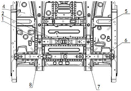
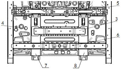
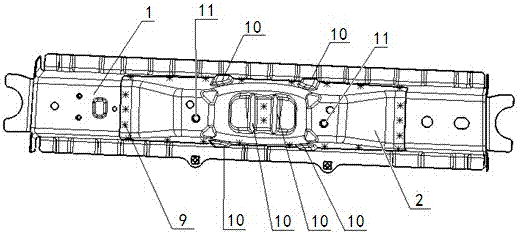
[0015] like Figure 1-Figure 5 The shown car transmission shaft installation and fixing structure includes a transmission shaft fixing crossbeam and a reinforcing crossbeam 3 which are welded and fixed on the front floor 4 and are located between the front crossbeam 5 installed on the front seats and the rear crossbeam 6 installed on the front seats. The transmission shaft fixing crossbeam and reinforcing crossbeam are symmetrically arranged on the lower surface and the upper surface of the front floor 4 respectively. The reinforcing crossbeam 3 is welded and fixed on the upper surface of the front floor, and the left and right ends of the reinforcing crossbeam are welded with the floor left b...


PUM


Abstract

The invention discloses an automobile transmission shaft installation and fixing structure, which comprises a transmission shaft fixing crossbeam fixed on the lower surface of the front floor, and the transmission shaft fixing crossbeam is composed of a crossbeam body and a transmission shaft fixing seat welded and fixed on the outer surface of the crossbeam body. On the upper surface of the front floor, a reinforcing crossbeam symmetrical to the fixed crossbeam of the transmission shaft is welded and fixed. The structure of the invention has better rigidity and can meet the requirements of bearing capacity and fixing reliability.

Description

technical field [0001] The invention relates to the field of automobile body structure, in particular to a novel installation and fixing structure of an automobile transmission shaft. Background technique [0002] At present, full-time four-wheel drive or timely four-wheel drive has become a must configuration for large SUVs. The intermediate drive shaft of four-wheel drive vehicles is divided into three-stage and two-stage types, and the two-stage intermediate drive shaft is more cost-effective than the three-stage type. , but the installation and fixation of the two-stage intermediate drive shaft is more difficult than the three-stage drive shaft. [0003] For example, patents CN201020539712.8 and CN201310574243.1 respectively disclose support structures for transmission shafts, but this support structure is mainly used for front and rear drive mini-cars, which cannot meet the needs of four-wheel drive SUV models for two-stage intermediate transmission shafts. Higher requ...

Claims


Application Information

Patent Timeline
Patent Type & Authority Patents(China)
IPC IPC(8): B60K17/24
Inventor 赵月欣尚广先李可易兵王远宏邹军
Owner CHONGQING CHANGAN AUTOMOBILE CO LTD
Why Eureka
Try Eureka