
Oil reservoir numerical simulation method and device based on downhole flow control equipment

A technology of flow control and numerical simulation, applied in the directions of measurement, production fluid, earthwork drilling and production, etc., can solve the problems of inapplicability and inapplicability of oil wells, and achieve the effect of improving recovery rate and simulation accuracy

Active Publication Date: 2015-11-25
PETROCHINA CO LTD
View PDF2 Cites 24 Cited by
  • Summary
  • Abstract
  • Description
  • Claims
  • Application Information

AI Technical Summary

Benefits of technology

This patented method allows scientists to study how fluids move within porous rock formations during drilling operations or other activities. By simulating these movements accurately, researches may help identify areas where there are problems related to fluid movement (such as reducing efficiency). These improvements allow more efficient resource utilization by optimizing hydrocarbon extraction from subterranean locations.

Problems solved by technology

This patented technical problem addressed in this patents relates to improving the accuracy and efficiency of simulating fluid flows during petrophysic simulations. Current methods involve setting up static conditions based solely upon data from previous models without considering impact factors like changes overtime caused by drilling operations.

Method used


Image

  • Oil reservoir numerical simulation method and device based on downhole flow control equipment
  • Oil reservoir numerical simulation method and device based on downhole flow control equipment
  • Oil reservoir numerical simulation method and device based on downhole flow control equipment

Examples


Embodiment Construction

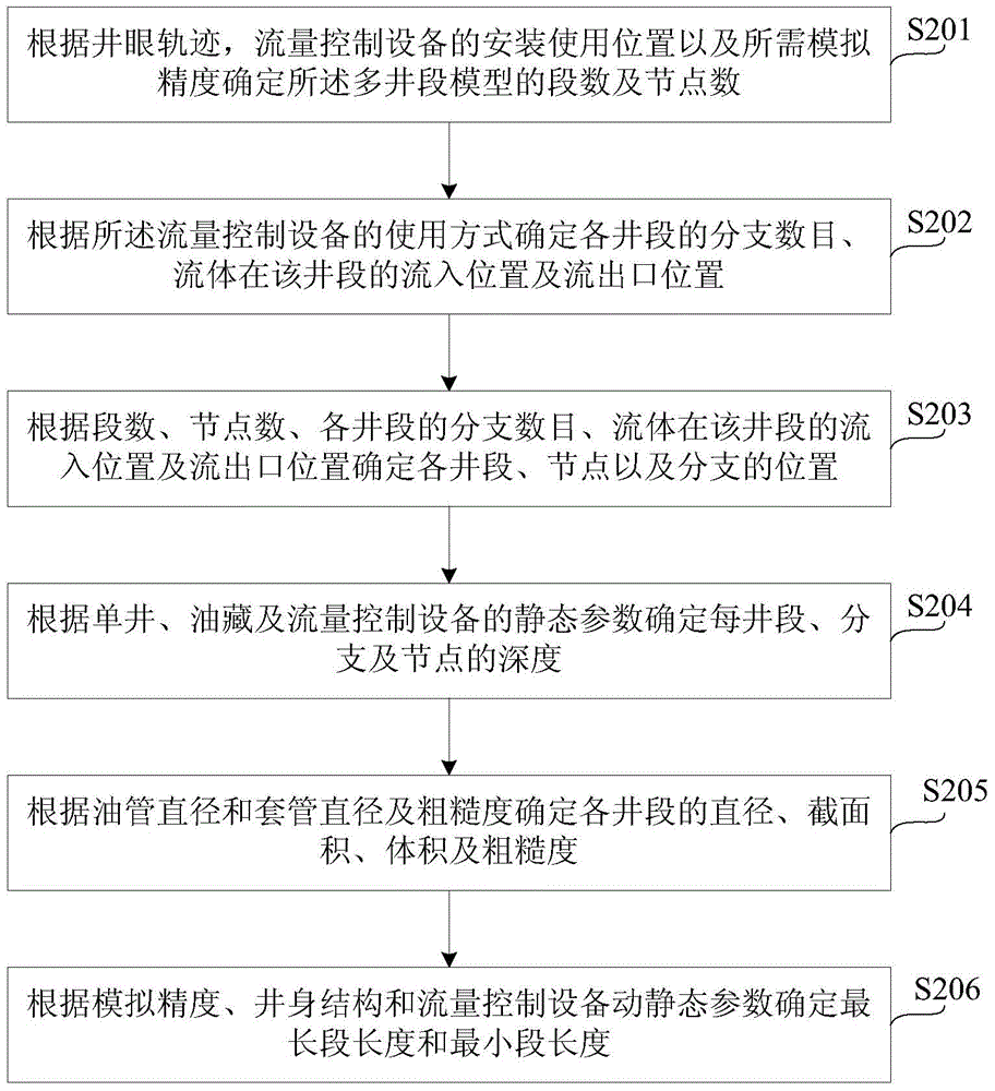
[0064] The following will clearly and completely describe the technical solutions in the embodiments of the present invention with reference to the accompanying drawings in the embodiments of the present invention. Obviously, the described embodiments are only some, not all, embodiments of the present invention. Based on the embodiments of the present invention, all other embodiments obtained by persons of ordinary skill in the art without making creative efforts belong to the protection scope of the present invention.

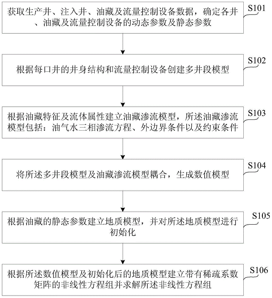
[0065] In order to solve the problems existing in the prior art, the embodiment of the present invention provides a reservoir numerical simulation method based on downhole flow control equipment, such as figure 1 As shown, the reservoir numerical simulation method includes:

[0066] Step 101: Obtain the data of production wells, injection wells, reservoirs and flow control equipment, and determine the dynamic parameters and static parameters of each well, rese...


PUM


Abstract

The invention provides an oil reservoir numerical simulation method and an oil reservoir numerical simulation device based on downhole flow control equipment. The oil reservoir numerical simulation method comprises the following steps: obtaining data of a production well, an injection well, an oil reservoir and flow control equipment; determining dynamic parameters and static parameters of each well, the oil reservoir and the flow control equipment; establishing a multi-well-section model according to the well body structure of each wheel and the flow control equipment; establishing an oil reservoir seepage model according to oil reservoir characteristics and fluid properties, wherein the oil reservoir seepage model comprises an oil-gas-water three-phase seepage equation, an outer boundarycondition and a restraint condition; coupling the multi-well-section model with the oil reservoir seepage model to generate a numerical model; establishing a geological model according to the staticparameters of the oil reservoir, and carrying out initialization on the geological model according to a relationship of original formation pressure distribution or pressure and depth as well as rock and fluid properties; and establishing a nonlinear equation set with a sparsity coefficient matrix according to the numerical model and the initialized geological model, and solving the nonlinear equation set.

Description


Claims


Application Information

Patent Timeline
Owner PETROCHINA CO LTD
Learn More