Stable speed reducer gear

A reducer, stable technology, applied in belt/chain/gear, mechanical equipment, components with teeth, etc., can solve the problems of poor stability, large contact gap, affecting the reducer, etc., to improve stability, prevent The effect of loosening and ensuring normal operation

Inactive Publication Date: 2015-11-25
CHANGZHOU WUJIN JINCHENG GEAR
View PDF4 Cites 0 Cited by
  • Summary
  • Abstract
  • Description
  • Claims
  • Application Information

AI Technical Summary

Problems solved by technology

[0003] In order to overcome the shortcomings of the existing gears with large contact gap, poor stability and affecting the normal operation of the reducer, the present invention provides a stable reducer gear

Method used


Image

  • Stable speed reducer gear

Examples


Embodiment Construction

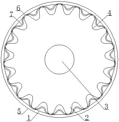
[0013] Such as figure 1 It is a schematic diagram of the structure of the present invention, a stable reducer gear, including a wheel body 1, a tooth body 2 and a shaft hole 3, the tooth body 2 is evenly distributed on the circumference of the wheel body 1, and the shaft hole 3 is located at the center of the wheel body 1 , The wheel body 1 is provided with a gear hole 4, a skirt 5 and a rim 6. The tooth holes 4 are uniformly opened on the circumference of the wheel body 1 and are spaced apart from the tooth body 2 . The skirts 5 are located on both sides of the circumference of the wheel body 1 . The rim 6 is an elastic ring, which is sleeved on the wheel body 1 and embedded between the skirts 5 . The rim 6 is provided with a guide groove 7, and the guide groove 7 is recessed in the tooth hole 4, corresponding to the tooth hole 4 one by one.

[0014] The gear hole 4, the skirt 5 and the rim 6 are set on the wheel body 1, and the gear hole 4 is used to replace the notch bet...


PUM


Abstract

The invention relates to the technical field of transmission gears, in particular to a stable speed reducer gear. The stable speed reducer gear comprises a gear body, tooth bodies and a shaft hole, wherein the tooth bodies are evenly distributed on the periphery of the gear body; the shaft hole is located in the circle center of the gear body; the gear body is provided with tooth holes, a skirt and a gear ring. The tooth holes, the skirt and the gear ring are arranged on the gear body, the tooth holes are used for replacing traditional notches between tooth bodies, and the stability of engagement is improved. The hole openings of the tooth holes are sleeved with the gear ring of an elastic structure, so that looseness is prevented, and contact tightness is improved. In the work process, the periphery of the gear body is sleeved with the gear ring through the skirt, and guide grooves in the gear ring are concaved in the tooth holes and in one-to-one correspondence to the tooth holes. In the rotation process, the gear matched with the gear ring makes contact with the gear ring firstly, and the gear ring is elastically squeezed under the guidance of the guide grooves and gradually inserted into the tooth holes, so that complete engagement with the gear body is realized. Seamless butt joint is carried out from loose to tight and from shallow to deep in the whole process, the connecting stability is greatly improved, and normal operation of a speed reducer is guaranteed.

Description

technical field [0001] The invention relates to the technical field of transmission gears, in particular to a gear of a stable reducer. Background technique [0002] Gear is a common mechanical transmission part, especially widely used in reducer. However, the gear structure of the existing reducer is single, and the contact gap between the gears is large, which leads to poor operation stability and affects the normal operation of the reducer. Contents of the invention [0003] In order to overcome the shortcomings of existing gears with large contact gap and poor stability, which affect the normal operation of the reducer, the present invention provides a stable reducer gear. [0004] The technical solution adopted by the present invention to solve the technical problem is: a stable reducer gear, including a wheel body, a tooth body and a shaft hole, the tooth body is evenly distributed on the circumference of the wheel body, and the shaft hole is located at the center o...

Claims


Application Information

Patent Timeline
Patent Type & Authority Applications(China)
IPC IPC(8): F16H55/17
CPCF16H55/17
Inventor 任志江
Owner CHANGZHOU WUJIN JINCHENG GEAR
Why Eureka
Try Eureka