
A stabilizer bar structure and automobile

A technology for stabilizer bars and automobiles, which is applied in vehicle components, transportation and packaging, interconnection systems, etc., can solve the problems of complex stabilizer bar structures, inability to achieve continuously variable rigidity, etc., to ensure driving safety and ride comfort. , the effect of taking into account the driving safety

Active Publication Date: 2017-09-29
BAIC MOTOR CORP LTD
View PDF5 Cites 0 Cited by
  • Summary
  • Abstract
  • Description
  • Claims
  • Application Information

AI Technical Summary

Problems solved by technology

[0005] The invention provides a stabilizer bar structure and a car, which are used to solve the technical defects in the prior art such as the complex structure of the stabilizer bar and the inability to realize continuous variable stiffness.

Method used


Image

  • A stabilizer bar structure and automobile
  • A stabilizer bar structure and automobile
  • A stabilizer bar structure and automobile

Examples


Embodiment 1

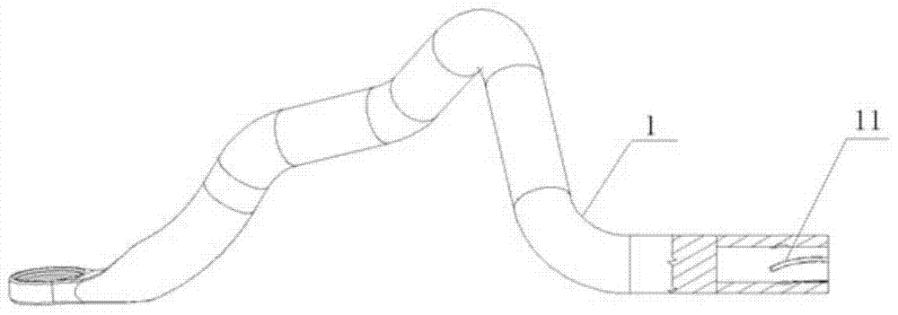
[0032] to combine Figure 1 to Figure 5 As shown, the stabilizer bar structure of the present invention comprises a left mounting rod 1, a right mounting rod 2, a left connecting rod 3, a right connecting rod 4, a left spring 5, a right spring 6 and an intermediate rod 7, the intermediate rod 7 is hollow, and The inner wall of the left end of the middle rod 7 and the inner wall of the right end are symmetrically provided with a left guide groove (not shown) and a right guide groove 71, and at least two first grooves 31 are arranged at intervals along the circumferential direction on the left end of the outer wall of the left connecting rod 3. A groove 31 is arc-shaped and the slope of the left end is greater than that of the right end, and there is a smooth transition between the left end and the right end. A first key 32 is provided on the right end of the outer wall of the left connecting rod 3, and the right end of the left connecting rod 3 is inserted into the middle rod 7 ...

Embodiment 2

[0046] The automobile of the present invention can be provided with the stabilizer bar structure of Embodiment 1, and the stabilizer bar structure can be arranged between the two front wheels of the automobile.

[0047] Further, the stabilizer bar structure can be set in a conventional way, for example, the middle bar of the stabilizer bar structure is connected to the sub-frame of the vehicle, and the left mounting rod 1 and the right mounting rod 2 of the stabilizer bar structure are respectively connected to the connecting rod of the car stabilizer bar.

[0048] The automobile of the present invention can realize continuously variable rigidity by installing the above-mentioned stabilizer bar structure, so that the ride comfort and driving safety of the automobile can be taken into account.


PUM


Abstract

The invention provides a stabilizer bar structure and an automobile. The stabilizer bar structure includes a left mounting rod, a right mounting rod, a left connecting rod, a right connecting rod, a left spring, a right spring and a middle rod. The rods are symmetrically arranged at the left and right ends of the middle rod, grooves and keys are respectively provided on the left and right ends of the outer walls of the left and right connecting rods, and the left and right connecting rods are respectively inserted into the left and right ends of the middle rod And each key is slidingly set in the corresponding guide groove, the left and right springs are arranged between the corresponding connecting rod and the middle rod, the left and right mounting rods are symmetrically arranged at both ends of the left and right connecting rods, and one end of the left and right mounting rods It is hollow and has a groove on the inner wall. The connecting rod is inserted into the installation rod and a raceway is formed between the groove and the groove of the installation rod, and balls are arranged in the raceway. The stabilizer bar structure can realize continuous adjustment of stiffness, so as to give consideration to both ride comfort and driving safety of the car.

Description

technical field [0001] The invention relates to an automobile component, in particular to a stabilizer bar structure and an automobile. Background technique [0002] The stabilizer bar is an important part of the car. Its main function is that when the car is driving along a curve, the force on the left and right wheels is unbalanced. The stabilizer bar can provide sufficient roll stiffness for the car through its own torsion, thereby reducing the weight of the car body. The roll angle improves the safety of the car. [0003] At present, the traditional stabilizer bar is a torsion bar spring made of spring steel, which is placed horizontally on the front and rear ends of the car. Left and right hanging lower brackets or shock absorber struts. However, the stiffness of the traditional stabilizer bar cannot change with the change of the roll angle of the car, especially it cannot achieve continuous variable stiffness, so it cannot guarantee the ride comfort and driving safet...

Claims


Application Information

Patent Timeline
Patent Type & Authority Patents(China)
IPC IPC(8): B60G21/055
Inventor 王浩力彭锋侯建勇陈立山
Owner BAIC MOTOR CORP LTD
Learn More