A body-mounted locomotive integral fuel tank structure

An integrated fuel tank and load-bearing technology, applied in the direction of locomotives, etc., can solve the problems that the fuel tank cannot participate in the load of the car body, the space utilization rate is not high, and the lightweight design of the car body cannot be satisfied, so as to meet the requirements of lightweight design, convenient installation, The effect of increasing stiffness

Active Publication Date: 2017-08-25
CRRC ZIYANG CO LTD
View PDF11 Cites 0 Cited by
  • Summary
  • Abstract
  • Description
  • Claims
  • Application Information

AI Technical Summary

Problems solved by technology

The existing problem is that the fuel tank cannot participate in the load bearing of the car body, the space utilization rate is not high, and it cannot meet the requirements of the lightweight design of the car body

Method used


Image

  • A body-mounted locomotive integral fuel tank structure
  • A body-mounted locomotive integral fuel tank structure
  • A body-mounted locomotive integral fuel tank structure

Examples


Embodiment Construction

[0041] The present invention will be further described below in combination with specific embodiments and accompanying drawings.

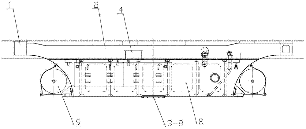
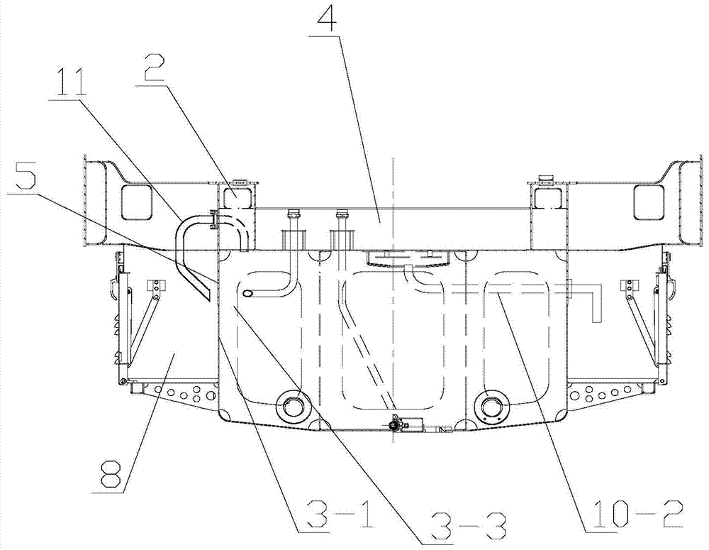
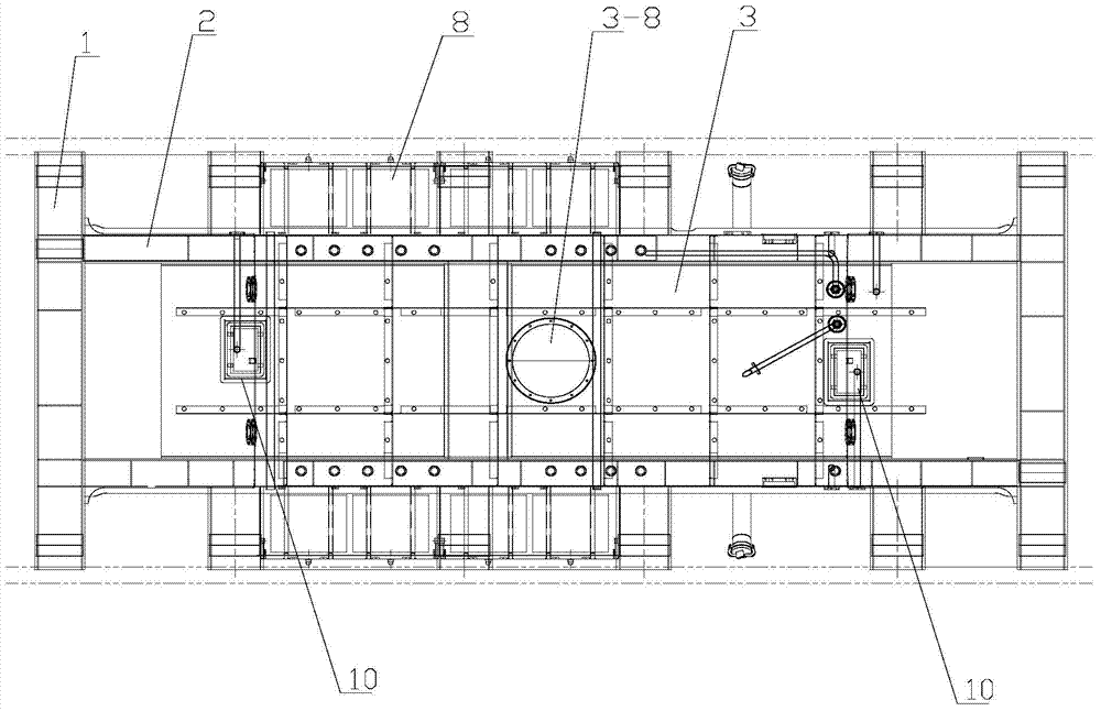
[0042] see Figure 1 to Figure 14 As shown, a body-loaded locomotive integral fuel tank structure includes a crossbeam 1, a longitudinal beam 2 and a fuel tank 3. The crossbeam 1 is connected to two ends of two longitudinal beams 2 arranged in parallel to form an I-shape, and the A reinforcing beam 4 is arranged between the root longitudinal beams 2 . There is an outer plate 5 extending vertically downward on the outer side of the longitudinal beam 2 , the fuel tank 3 is placed between the two longitudinal beams 2 , and both sides of the fuel tank 3 are connected and fixed to the outer plate 5 . The fuel tank 3 is connected and fixed on one half of the outer plate 5 .

[0043] see Figure 4 to Figure 6 , the inside of the longitudinal beam 2 is provided with a group of air ducts 6 for the positive pressure ventilation of the diesel engine room, ...


PUM


Abstract

The invention discloses an integral oil tank structure of a car body bearing type locomotive, which comprises a crossbeam, a longitudinal beam and a fuel tank. The crossbeam is connected between two parallel longitudinal beams, and the outer side of the longitudinal beam has an outer plate extending vertically downward. , the fuel tank is placed between two longitudinal beams, and both sides of the fuel tank are welded and fixed to the outer plate. A dirt collection tank is installed in the fuel tank, the fuel tank cover is covered on the dirt collection tank cover, the opening size of the oil hole is larger than the oil leakage hole, and the fuel tank cover and the dirt collection tank cover are welded and fixed along the edge of the oil hole. The outer side plate of the longitudinal beam of the present invention is used as the main vertical plate of the fuel tank body, and is welded together with the outer wall of the fuel tank, thereby improving the rigidity of the whole fuel tank. The welded fuel tank is welded into a whole with longitudinal beams, beams, and reinforced beams to form an integral fuel tank, which can not only increase the bearing capacity of the fuel tank body, but also increase the rigidity of the middle structure. Under the same load requirements, the vehicle body can be significantly reduced. The weight meets the requirements of the lightweight design of the car body.

Description

technical field [0001] The invention relates to a fuel tank, in particular to a locomotive load-bearing integral fuel tank structure. Background technique [0002] Currently, conventional locomotive fuel tanks are an independent part that is designed separately from the locomotive underframe. The problem is that the fuel tank cannot participate in the vehicle body load, the space utilization rate is not high, and it cannot meet the requirements of the lightweight design of the vehicle body. [0003] Therefore, how to solve the above technical problems has become an urgent problem for those skilled in the art. Contents of the invention [0004] The object of the present invention is to provide an integral fuel tank structure of a body-mounted locomotive, which can completely solve the above-mentioned problems in the prior art. [0005] The purpose of the present invention is achieved through the following technical solutions: [0006] An integral fuel tank structure for ...

Claims


Application Information

Patent Timeline
Patent Type & Authority Patents(China)
IPC IPC(8): B61C17/02
Inventor 景松柏吴凯王江花陈传彬陈强靳宁叶萍隆孝军江太宏伍华
Owner CRRC ZIYANG CO LTD
Why Eureka
Try Eureka