
Engaging and disengaging mechanism of electronic core insertion lock

A clutch mechanism and mortise lock technology, applied in building locks, building structures, non-mechanical transmission-operated locks, etc., can solve the problems of poor universality of electronic mortise locks, and achieve the effect of good universality

Active Publication Date: 2015-12-02
肖钧
View PDF12 Cites 4 Cited by
  • Summary
  • Abstract
  • Description
  • Claims
  • Application Information

AI Technical Summary

Problems solved by technology

It solves the problem of poor versatility of electronic mortise locks in the prior art due to the different restrictions on opening the door by the inner and outer handles, and the locks for left-opening doors and the locks for right-opening doors have different lock bodies.

Method used


Image

  • Engaging and disengaging mechanism of electronic core insertion lock
  • Engaging and disengaging mechanism of electronic core insertion lock
  • Engaging and disengaging mechanism of electronic core insertion lock

Examples


Embodiment 1

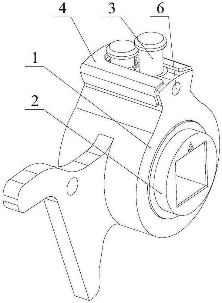
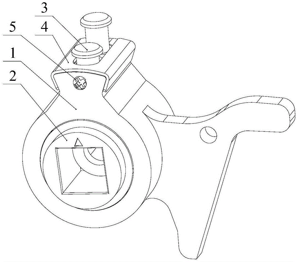
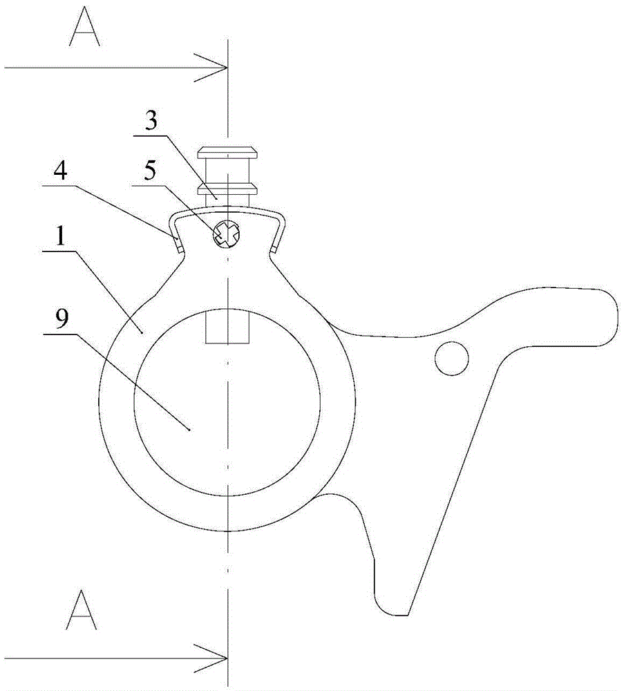
[0046] Such as Figure 1~5 As shown, a clutch mechanism of an electronic mortise lock, including:

[0047] The main transmission part 1 has a cylindrical through hole 9, and the side wall of the main transmission part 1 has two clutch shaft installation holes 17 arranged at intervals, and each clutch shaft installation hole 17 communicates with the through hole 9. In this embodiment , in order to make the fit better, the axis of the clutch shaft mounting hole 17 is perpendicular to the axis of the through hole 9;

[0048] Two clutch parts 2, each clutch part has a fitting part 24 that stretches into the through hole and is rotatably matched with the through hole. Both have a limit groove 11 that matches the mounting hole of the clutch shaft;

[0049] The clutch shaft 3 is slidably installed in the corresponding clutch shaft installation hole 17, and the main transmission part is locked by controlling the clutch shaft to extend into the corresponding limiting groove, and the ...

Embodiment 2

[0064] Such as Figure 9 As shown, the difference between this embodiment and embodiment 1 is that the matching anti-off parts and the main transmission part are slightly different from embodiment 1. In this embodiment, the side wall of the protrusion of the main transmission part 1 is provided with a limit Position chute 22, the anti-off part has a sliding part 23 that cooperates with the limit chute 22, and an anti-off part 26 that cooperates with the middle side wall of the protrusion, and the anti-off part 26 has a notch for the clutch shaft to pass through, And the notch cooperates with the limit ring to prevent the limit ring from breaking away from the mounting hole of the clutch shaft.


PUM


Abstract

The invention discloses an engaging and disengaging mechanism of an electronic core insertion lock. The engaging and disengaging mechanism comprises a main transmission part, two engaging and disengaging parts and engaging and disengaging shafts, wherein a through hole is formed in the main transmission part, and two engaging and disengaging shaft mounting holes communicated with the through hole are formed in the side walls of the main transmission part; each engaging and disengaging part is provided with a matching portion rotatably matched with the through hole, and a limiting groove is formed in the outer side wall of each matching portion; the engaging and disengaging shafts are slidably installed in the engaging and disengaging shaft mounting holes, and the main transmission part is locked or unlocked by controlling the engaging and disengaging shafts to extend into and out of the corresponding limiting grooves. According to the engaging and disengaging mechanism, by limiting one of the engaging and disengaging shafts, the end of the engaging and disengaging shaft is made to extend into the through hole and be matched with the limiting groove of the corresponding engaging and disengaging part, thereby the engaging and disengaging part matched with the first engaging and disengaging shaft is relatively fixed with the main transmission part and can rotate together with the main transmission part, and a lock of a leftward-opened door and a lock of a rightward-opened door can be interchanged by selecting and limiting the different engaging and disengaging shaft.

Description

technical field [0001] The invention relates to an electronic mortise lock, in particular to a clutch mechanism of the electronic mortise lock. Background technique [0002] There are two handles installed on the lock body of the electronic mortise lock, one is on the outside of the door, and the other is on the inside of the door. The handle outside the door is unlocked. The principle of unlocking is: before unlocking, the clutch plate and the clutch body connected to the outside handle in the lock body are in idling connection, and the handle is in a no-load state; when unlocking, use the electronic key to drive the motor through the circuit to control the lock. The clutch structure in the body pushes the clutch pin into the clutch body. At this time, the clutch plate connected to the door handle is connected to the clutch body. The clutch plate and the clutch body are closed, and the handle outside the door can drive the clutch structure to rotate, and the clutch structur...

Claims


Application Information

Patent Timeline
Patent Type & Authority Applications(China)
IPC IPC(8): E05B15/00E05B47/00E05B63/04
Inventor 肖钧
Owner 肖钧
Learn More